Accurate design of crossover inductance based on three-way loudspeaker system
1 Introduction The speaker system using power frequency division has a simple structure, low cost, and can obtain very high playback quality, so it is most commonly used in modern high-fidelity playback systems. Its performance is inextricably related to the various indicators of the speaker, the performance and accuracy of the crossover circuit and inductance components, and accurate calculation of the inductance parameters is the key to success. (5) The loss is flat in the entire frequency band, and there is basically no "peak" and "deep valley". (1) Calculate the crossover inductances L1, L2, L3, L4 and the crossover capacitors C1, C2, C3, C4. Phone Screen Protector,Screen Protectors,Hydrogel Film Sheets,Mobile Screen Protector,Ceramic screen protector Guangdong Magic Electronic Limited , https://www.magicmax.cc
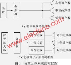
The frequency divider of the loudspeaker system is divided into two types: pre-frequency division and power frequency division. The pre-frequency division is the frequency division generated by the electronic components in the pre-stage circuit, and then the high, middle and woofer speaker systems are driven by their respective power amplifiers, as shown in (1a), which belongs to the small signal active frequency division. The power frequency division is a passive frequency division circuit between the power amplifier and the speaker, which is composed of inductance, capacitance and resistance elements, as shown in (1b). 
2 Requirements for frequency divider circuits and components
(1) The smaller the error between the DC resistance and inductance of the inductive element in the circuit, the better. Moreover, in order to make the frequency response curve flat, it is best to use air-core inductors.
(2) The loss of capacitive elements in the circuit is as small as possible. It is best to use metalized polypropylene capacitors for audio.
(3) Distribute each speaker unit to a relatively flat signal power and protect the high-frequency speaker.
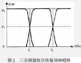
(4) The transmission power characteristics of the combined frequency division of each channel should meet the requirements of the characteristic curve shown in Figure 2 (P0 is the maximum value and P1 is the value of the corresponding frequency division points f1 and f2). The amplitude between the power at the crossover point and the maximum power should meet the range of P1 (= 0.3 ~ 0.5) P0. 
3 Calculation of the parameter value of frequency-divided inductance and capacitance
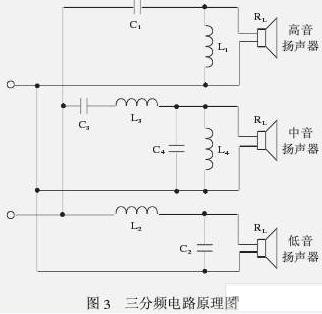
The following uses a three-way frequency divider as an example to illustrate the calculation of its parameters, as shown in Figure 3. 
In order to obtain the ideal spectrum characteristic curve, it can be taken in theoretical calculation: C1 = C4, C3 = C2, L1 = L3, L4 = L2, the frequency of crossover point is f1, (f2 see figure 2), then the crossover point ω1 = 2πf0 , Ω2 = 2πf2. It is also assumed that the impedances of high, medium and low speakers are the same as RL. 12 dB attenuation per octave. 
(2) Experiment to modify the values ​​of C1, C2, C3, C4, L1, L2, L3, L4
For the sake of accuracy, the values ​​of C1, C2, C3, C4, L1, L2, L3, and L4 can be slightly adjusted by experimental methods to meet the requirements of the design curve (see Figure 2). That is, the frequency response curve is drawn through experiments to obtain the optimal values ​​of C1, C2, C3, C4, L1, L2, L3, and L4. If there are no experimental conditions, this step is not necessary. After calculating the value of the capacitance inductance, the inductance value can be calculated.