PID feedback circuit schematic
The current outputted by the PID control system is subjected to operational amplification and driving to obtain the required compensation current magnetic potential I2eWe, and the operation and amplification link is proportional control in the automatic control system. The biggest disadvantage of proportional control is that there is a residual. When there is a higher requirement for control quality, it needs to be based on the proportional control, plus the integral control function that can eliminate the residual. Even if the deviation is small in the differential control system, as long as there is a change trend, it can be controlled immediately, and has the characteristics of advanced control. Therefore, the PID controller is used in the differential current compensation loop. The PID feedback circuit is shown in the figure. It can not only control quickly, but also eliminate the residual and has better control performance. 2.0 Rgb Computer Speakers,Rgb Light 2.0 Channel Speaker,Knob Control Function 2.0 Speaker,Rgb Without Bluetooth Speaker Comcn Electronics Limited , https://www.comencnspeaker.com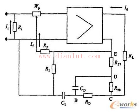
The working process of the PID operation circuit is as follows: When the input signal Ii has a step change, the CD, C1 is equivalent to a short circuit, and the input signal suddenly jumps to the differential action maximum value. Then, as the CD is charged, the negative feedback voltage gradually rises, and the output current I0 gradually decays. At the same time, CI is also charged. As the voltage across CI increases, the negative feedback effect gradually decreases, and the output current I0 rises slowly.