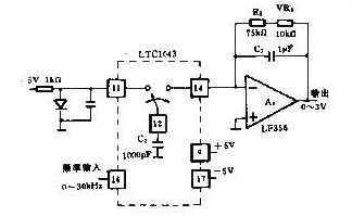
Voltage/frequency conversion circuit diagram
Voltage/frequency conversion circuit The figure shows the voltage/frequency conversion circuit diagram. A linearly good voltage/frequency conversion circuit is more complicated. This circuit A1 uses the LTC1043, and the A2 uses the LF356. The 16th pin of A1 is the frequency input. If 16 pin is high level at the beginning, pin 12 and pin 13 are shorted, and C2 is charged instantaneously. If the 16 pin becomes low level, the falling edge causes the 12 pin and the 14 pin to be shorted, the C2 charge is discharged, and the discharge current passes through the feedback loop of A2, and the instantaneous A2 output becomes negative. Due to negative feedback, the output is positive before the inverting input of A2 is zero. Repeat the above operation, the A2 output voltage is proportional to the 16-pin input frequency of A1. The feedback resistance of A2 determines its DC gain. Adjust potentiometer VR1 (10kΩ), so that the input frequency is 30kHz, A2 output is 3V, so for the input 0~30kHz frequency, 0~3V output voltage can be obtained, the linearity is about 0.005%. Aluminum Zinc Alloy Die Casting Blank Aluminum Zinc Alloy Die Casting Blank,Metal Structure Zinc Casting,Custom Made Precision Die,Zinc Aluminum Alloy Casting Dongguan Metalwork Technology Co., LTD. , http://www.diecast-pro.com