Mobile phone charger circuit schematic and universal charger
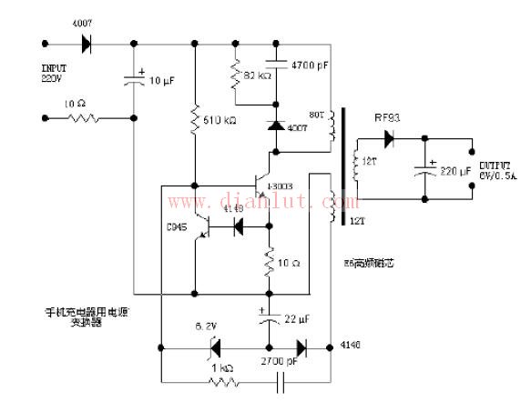
Mobile phone charger circuit schematic and universal charger The universal charger is a typical mobile phone charger. It rectifies the mains 220V Power Supply through a 1N4007 diode and sends it to the corresponding oscillation circuit. 220V AC input, one end through a 4007 half-wave rectification, the other end through a 10 ohm resistor, filtered by a 10uF capacitor. This 10 ohm resistor is used for protection. If an overcurrent occurs due to a fault in the back, the resistor will be blown to avoid causing a larger fault. The right 4007, 4700pF capacitor and 82KΩ resistor form a high-voltage snubber circuit. When the switch tube 13003 is turned off, it is responsible for absorbing the induced voltage on the coil, thereby preventing high voltage from being applied to the switch tube 13003 and causing breakdown. 13003 is the switch tube (complete name should be MJE13003), withstand voltage 400V, collector maximum current 1.5A, maximum collector power consumption is 14W, used to control the on and off between the primary winding and the power supply. When the primary winding is continuously turned on and off, a varying magnetic field is formed in the switching transformer, thereby generating an induced voltage in the secondary winding. 3D Printer Shenzhen Yidashun Technology Co., Ltd. , https://www.ydsadapter.com