CAN network security with XC2300 series microcontroller
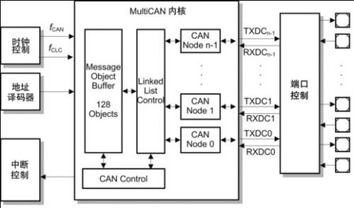
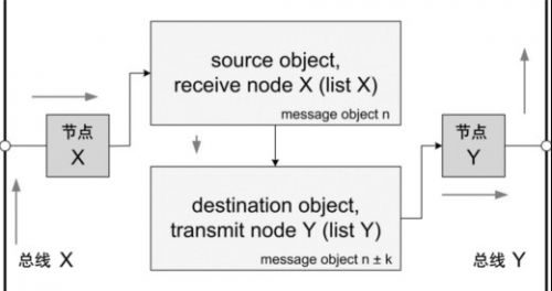
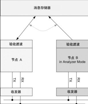
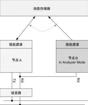
The XC2300 is a new family of microcontrollers specifically designed for automotive safety applications, particularly airbag systems and electric power steering applications. The product line is designed to enable automotive electronic security systems to be scalable, hardware and software reuse and compatibility. The XC2300 series is equipped with a high-performance central processing unit (CPU) and a rich set of peripherals. This article uses the MultiCAN module as an example to illustrate how to use these features to support security applications and how to further meet the specific security requirements for software and CAN software through hardware support. This article refers to the address: http:// Introduction to MultiCAN MultiCAN is a proven, expandable module that provides up to four independent CAN nodes that are fully ISO 11898 compliant. The number of message objects that can be shared by all CAN nodes is up to 128. The linked list assigns message objects to specific nodes, providing great flexibility for system layout. The message object implements the autonomous gateway function through internal contact. Message objects that are not assigned to a particular node are available for the FIFO structure. All nodes support the analyzer function as a bus passive component to connect to the bus system. Figure 1 XC2300 security product line MultiCAN module with up to 4 independent CAN nodes and 128 message objects Flexible FIFO structure All message objects shared by the CAN node can be individually assigned to a specific linked list, and each linked list is bound to a specific node. For example, linked list 1 corresponds to node 0, linked list 2 corresponds to node 1, and so on. Linked list 0 is an attached linked list of all unallocated message objects. These linked lists use a double-chained linked list structure. This architecture provides a high degree of flexibility in the use of message objects on different CAN nodes. At the same time, unused message objects are available for the FIFO structure. These FIFOs can be assigned to specific CAN nodes as well as to a linked list of unused nodes. Since only the message input to the node needs to be compared with the message object assigned to the linked list, the judgment speed of the message object is improved. Of course, you need to link the FIFO base message object to a specific node linked list. Gateway function There are usually multiple CAN networks in an embedded application that run at different speeds for the application. Some messages need to be transferred from one bus system to another. The gateway function is very effective for implementing the above applications, and it is also possible to combine gateway and FIFO functions. For example, when transmitting a message with a high frequency from a high-speed CAN bus to a low-speed CAN bus, combining the gateway and FIFO functions, it is possible to implement such message transmission without increasing the CPU load. Analyzer mode All nodes of the CAN network usually use the CAN protocol, which responds to the message and confirms it. In the analyzer mode, the CAN node listens to the bus and does not actively use the protocol for transmission. This feature is valuable for a variety of applications. For example, the baud rate is detected without affecting the operation of the bus. This feature can also be used to implement hot swapping of a running CAN network. More advantages include simultaneous analysis and drive delay measurements. This can be used for frame timing measurements and adjusts the bit timing value based on the physical CAN bus conditions. It also provides detailed information on the errors detected, making it easy to analyze the cause of the error. For example, the last error code (LEC) bit field, the readability of all error counters, and the flexible downgrade of the error alarm level. Analyzer mode for secure applications Safety applications have special requirements, such as adding redundant components to critical paths. In CAN networks, CAN nodes and CAN transceivers are in this critical path. Message transmissions through nodes may be blocked, and even worse, communication from other nodes on the bus may be disturbed. The Infineon XC2300 series of microcontrollers provides up to four independent CAN nodes and can be used for error detection in analyzer mode in a variety of configurations. Errors from the physical CAN bus to the message memory can be detected using 2 CAN nodes and 2 independent CAN transceivers. The second CAN node operates in analyzer mode, listens to the bus, and does not actively use the protocol for transmission. The advantage of this configuration is that errors caused by the CAN transceiver can also be detected. The disadvantage is the cost. Another configuration is to abandon the second CAN transceiver, which is lower in cost but does not detect errors caused by the transceiver. In both configurations, the nodes are processed asynchronously because the internal protocol processor requests information in the order of one message object and the other. Two different message objects are used and compared by software to verify the correctness of the information received. This can even reveal problems between the protocol processor and the message store. Figure 2 Autonomous transmission of CAN messages using the gateway function, without additional CPU load Software is the most critical part of the built-in security application. Since software is often considered “untrustworthyâ€, mandatory special measures must be taken to meet security requirements. Additional hardware integrated in the microcontroller can meet these requirements. The upcoming XC2300 series of new devices offers the following hardware features. Memory protection unit The Memory Protection Unit (MPU) distinguishes between different software tasks, allocates storage for each task, and runs each task in its own designated storage area. If a task attempts to access a storage area that is not assigned to the task, the access is blocked and a trap is triggered. Other measures can be taken, such as sending an error message to an external watchdog, closing a task that caused the error, cutting off the safety path, or even restarting the microcontroller. The MPU separates program memory, data memory, and I/O memory, controls read and write, and performs memory access. Figure 3 Using the analyzer mode to build a complete redundant path to detect blocked or interfered message transmissions (including errors caused by CAN transceivers) CRC or storage check module To ensure the integrity of stored information such as programs and data, a CRC (Cyclic Redundancy Check) is required. The value of the CRC is usually calculated for the information block and stored in a certain storage area. When checking the information, the value of the CRC is recalculated and compared to the stored CRC value. This can be done either at the start of the isochronous point or periodically during the run. CRC can also protect data communications like the CAN protocol and protect individual critical security data or variables that require the highest data integrity. Of course, software can also do CRC calculations very flexibly, but using dedicated hardware is more efficient because it speeds up the calculations and frees the CPU from such tasks. With read and write functions such as DMA (Direct Memory Access), CRC checking can be performed in the background without CPU involvement, separating CRC checking from peripheral initialization. ECC on FLASH and RAM While the CRC mechanism is used in the storage area and is started by the CPU, the CRC storage content protection concept can be extended, and such a mechanism is added to the storage module itself. An additional memory checksum generated by a special ECC (Error Correcting Code) polynomial protects individual stored data. Through this checksum, unexpected changes in the data can be detected and automatically corrected before the data is submitted to the CPU. This is the main difference between CRC and ECC. For example, two bit errors can be detected, one of which can be corrected, depending on the polynomial used and the length of the stored ECC value. When a write access is made, an ECC value is generated, and in addition to storing the written data, the generated ECC value is also stored. When a read access is made, the ECC of the data is recalculated and autonomously compared to the stored values. This mechanism is implemented by hardware, and from a system perspective, there is no need to increase the bus cycle. Currently, ECC is generally used for flash memory, but for security needs, RAM memory also uses ECC. Figure 4 Using the analyzer mode to build a low-cost redundant path to detect blocked or interfered message transmission Conclusion Infineon's new XC2300 series of microcontrollers are designed for safety-critical systems and support multiple parallel CAN networks. The gateway function enables internal connections between different CAN networks, and the MultiCAN module's analyzer mode adds redundancy to detect potential errors. Other features such as the last error code (LEC) bit field, all readable error counters, and flexible downgrades of error alarm levels make potential errors more discoverable. Last but not least features include MPU (Storage Protection Unit), CRC (Cyclic Redundancy Check) and ECC (Error Correction Code), which detect critical hazards and ensure the security of the running software. Only a complete system of various hardware and software features can be combined to ensure that the CAN system is suitable for the application. Product categories of Universal Stylus Pen, We are Specialized Stylus Pen manufacturers from China, The Universal Stylus Pen can be worked on android phones / apple phones and all brands capacitive touch screens. We have perfect after-sale service and technical support. Looking forward to your cooperation. Phone Stylus Pen,Touchscreen Stylus Pen,Stylus Pen For Android,Tablet Stylus Pen Shenzhen Ruidian Technology CO., Ltd , https://www.wisonens.com