Inverter dummy load usage - Database & Sql Blog Articles
How to connect the inverter dummy load: The dummy load is connected between the DC storage capacitor and the three-phase IGBT. In the circuit, it is usually connected to the copper busbar or fast-melting. There is a fast-fusion direct connection. No quick-melt removal of a connection. The copper row can be used, which is actually disconnecting the positive power supply of the three-phase inverter IGBT from the DC storage capacitor. Behind the capacitor, such as between the charging contactors, the amount of power stored by the DC capacitor is sufficient to blow up the IGBT when there is a problem with the inverter circuit.
Freezer Condenser
1. Material: Bundy tube (steel tube coated with copper)
2. Structure: Bundy tubes welded with steel wines
3. Painting: Cathode electrophoretic painting(black)
4.
Can produce according to drawing or sample supplied by clients, also
can help the clients design and produce different condensers.
Freezer Condenser,Freezer Condenser Unit,Deep Freezer Condenser,Fridge Freezer Condenser FOSHAN SHUNDE JUNSHENG ELECTRICAL APPLIANCES CO.,LTD. , https://www.junshengcondenser.com
Add two 25w 220V power supply bulbs at the disconnection point. The purpose of using two is DC loop voltage is about 540V. The pressure resistance of a single bulb is not enough. When there is a problem with the inverter circuit, the bulb has a limited flow to protect the inverter module. 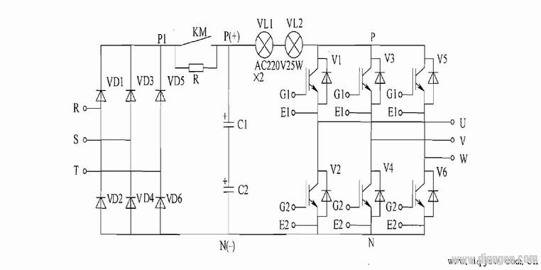
Power-on process:
No load: The output is not connected to the load.
A: The inverter does not run. The upper bulb will light up, indicating that at least one of the three inverter modules is leaking from the upper and lower bridge IGBTs. This problem is sometimes not indicated when the voltage is low, but when the DC voltage is 540V. A large leakage current has occurred, indicating that there is a problem with the internal insulation of the module. If this problem occurs, it can be removed by a single IGBT. If the U-phase bulb is not turned off, it means that the U-phase is broken.
B: There is no problem after power-on, but when it is running, the brightness of the bulb changes with the frequency. Explain that the one-phase upper bridge or the lower bridge is damaged in the three-phase module. For example, suppose that the U-phase upper bridge V1 receives the trigger excitation signal and is saturated, and the damaged U-phase lower bridge V2 and the already saturated-on V1 form a short circuit of the power supply, and thus emit light.
C: After power-on and running, it is not bright. At this time, the AC output of the pointer meter can be used to measure the three-phase output voltage, whether it grows evenly with the frequency and the three-phase balance. At this point, the basic problem of the module is not big, and the load experiment can be carried out. (Source: http://)
D: The power-on and running bulbs are not bright. Measuring the voltage imbalance of the three-phase output means that the internal phase of the IGBT is open, causing the internal resistance of the conduction to increase and approaching the open state.
How to measure such a problem:
1. Use the DC file of the pointer multimeter to measure the voltage between the three-phase output and the ground or the incoming neutral line. Under normal circumstances, the DC component is almost zero. If a DC voltage appears, one of the bridges of one of the upper and lower bridges is poorly connected. The positive and negative half waves of the output are asymmetrical.
2. Measure the three outputs and the positive and negative terminals of the DC bus voltage. Under normal circumstances, the DC bus voltage is divided equally. If a phase measurement occurs, it is greater than one-half of the bus voltage or directly close to the bus voltage. This phase IGBT half-bridge Poor conduction.