Design and Realization of Lightweight Shift System for Passenger Cars Based on CAN Bus
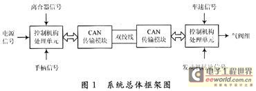
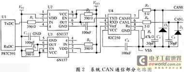
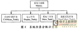
Design and Realization of Lightweight Shift System for Passenger Cars Based on CAN Bus 1 Introduction With the rapid development of the social economy, urban traffic is getting busy, and traffic safety issues are getting more and more attention. During the driving of the vehicle, the driver must adjust the driving direction and speed of the vehicle in time according to changes in road and traffic conditions, so that the car can obtain good driving performance and fuel economy performance. Frequent gear changes make the driver easily fatigued and distracted, resulting in increased traffic accidents. This article introduces the design of a light-duty shifting system for passenger cars based on CAN bus. The mechatronics technology is used to realize passenger car shifting. The system is mainly developed and designed in conjunction with the shift system of the passenger car, including two nodes before and after, the front node is the handle control command node, and the rear node is the execution control node. The overall system frame is shown in Figure 1. 2 System application design 2.1 System hardware structure and control principle In order to make the system meet the design requirements of responsiveness and high reliability, the control units of the front and rear nodes all use the P87C591 single-chip microcomputer produced by Philips. He successfully included the PelICAN function of the Philips semiconductor SJAl000 CAN controller, which meets the system design requirements. The circuit diagram of CAN communication part of the main control system is shown in Figure 2 [1]: The collection of gear, vehicle speed and engine speed signals in the system is completed by the Hall element A3144EU. After the signal is amplified, it is isolated by the photocoupler TLP521 and sent to the CPU. After logical operation, the CPU isolates the output signal through the photocoupler and sends it to a high-power field effect tube. The field effect tube drives the solenoid valve to control the cylinder action to complete the corresponding gear shift. The main control process of the system is: the front node collects signals in real time according to the position of the handle and the opening and closing of the clutch switch and processes it into a gear command after logical judgment, and transmits it to the rear node through the CAN bus, and the rear node receives the gear After the command, combined with the vehicle speed, engine speed and current gear to determine the timing of the shift, and then issued an action command to the actuator. The actuator makes the corresponding solenoid valve start to move according to the instruction requirements, so as to control the movement of the corresponding cylinder to realize the shift of the gear. After the gear shift is completed, the feedback signal is also processed to determine the completion of the shifting action, and then the next operation is made. The vehicle model has 5 upper gears and one reverse gear, using electronically controlled gas operation. Its specific gears and solenoid valve positions are shown in Figure 3. As shown in Figure 3, when valve 1 is vented and valve 2 is vented, the piston is pushed to the right end of the cylinder, and the fork is pushed to a predetermined position by the piston rod, which is defined as the KA layer; when valve 1 is vented, valve 2 is vented At the time, it is defined as the KC layer; when both valves are cut off, due to the return spring in the gearbox, it will be automatically positioned to the middle layer, defined as the KB layer. After the level is selected, the two upshift gas valves at the corresponding positions are used to achieve up and down movements in different directions, thereby completing the predetermined gear selection and gear shifting actions. 2.2 System software design The actual application requires high real-time performance and reliability of the system. In the software design, the programming method of the multi-task real-time operating system μC / OS-Ⅱ is used, which decomposes the application program into several independent processes, and then creates a monitoring. Process, monitor the operation of each process, so as to ensure the real-time and reliability of the system operation [2]. The system uses Keil C51 compiler, combined with the technical characteristics of the single-chip P89C591 used, transplanting a μC / OS-Ⅱ operating system that supports P89C591 includes: (1) Set a constant value in OS_CPU.H with #define to control the growth direction of the task stack. (2) Declare 10 data types in OS_CPU.H. (3) Use #define to define 3 macros in OS_CPU.H. (4) Write 6 simple C language functions in OS_CPU.C, namely initialize task stack, task creation hook function, task delete hook function, task switching hook function, statistical task hook function and timing hook function . (5) Write 4 assembly language functions in OS_CPU_A.ASM. The system needs to create a total of 4 tasks. The system task allocation is shown in Figure 4. The CAN bus scanning task regularly scans the registers of the CAN bus for receiving the handle position signal sent by the front node. Display tasks are mainly responsible for display, refresh, etc., and are used to observe the completion of actions during debugging. The main task of the system is to perform functions such as logical analysis and judgment of data and overrun alarm. The data collection task will scan each data collection port in real time to collect parameters such as vehicle speed and engine speed. The main function is responsible for system initialization and task creation, startup, etc. Various tasks can communicate with each other through semaphores, message queues, etc. to ensure that tasks are executed in real time and synchronized. 3 System communication mechanism design The requirements of the portable shift system for the communication system are: reliable data transmission, high real-time performance, high transmission rate, and low bit error rate [3]. As a serial communication network that effectively supports distributed control or real-time control, CAN bus has strong flexibility, simple expansion possibilities, excellent real-time communication, and reliability and error detection capabilities of communication, which can be applied to Various harsh electronic environments have become the preferred form of network communication bus for automobiles. The model structure of the CAN bus has only three layers: the physical layer, the data link layer, and the application layer. The transmission medium is twisted pair, and the communication rate can be up to 1 Mb / s (40 m). Its communication method is flexible, and no station address is required. Node information, using non-destructive bus arbitration technology, to meet real-time requirements. Based on the study of the CAN 2.0B specification, the solution of the custom communication protocol is used to realize the communication between the two nodes before and after the system. The front node sends a command, and the back node does not send a confirmation signal after receiving it. The front node judges whether it is correct after receiving the information from the back node. If it is incorrect or cannot be received within the specified time, the command is reissued, and the retransmission exceeds the specified The number of times is a communication failure; the rear node sends a message, and the front node does not send a confirmation message after receiving it. If the front node fails to receive it within the specified time, it is a communication failure. The basic structure of the node data frame is defined as follows: Each node data frame in the system is distinguished by ID, and each node can define multiple different data frames to transmit different information. System anti-interference design The system will take measures from both hardware and software to comprehensively prevent the impact of interference on the work of the microcontroller system. The hardware is mainly to cut off the interference from the transmission channel and the power line. In the design, the application of filter capacitors, optocouplers, and reasonable component layout and wiring can effectively suppress the interference of distributed capacitance, electromagnetic mutual inductance, and magnetic leakage interference. At the same time, the scientific grounding of the PCB board solves the problem of signal integrity and improves the electromagnetic compatibility (EMC) of the PCB board. The software aspect guarantees the normal operation of the program through instruction redundancy, software traps and watchdog technology, and effectively solves the problems of running and dead loops during the running of the program. 5 Conclusion The passenger car light shift system changes the manual shift to electronically controlled light shift, which makes the vehicle get better shift comfort and economy, completely realizes the passenger car shift, and retains the high efficiency of the mechanical transmission, The advantages of low cost and simple structure make full use of the characteristics of fast response and high controllability of electric control, which is in line with the development direction of electronic, intelligent and humanized automobile technology. The innovation of this article is to abandon the single-task mode of the previous single-chip system software programming and adopt the programming method of embedded real-time multi-task operating system μC / OS-Ⅱ, so that the real-time performance of the system is greatly improved. It has been proved by practice that the system runs reliably and the communication is normal, and has reached a high performance index. The system only needs a few adjustments and can be applied to all types of passenger cars, with broad development and application prospects.
As we all know that the parents all over the world pay more attention on children education, so more and more businessman do education laptop deals, therefore education laptop is becoming one of the most important fields no matter on customizing laptop or brand one. There are different series according to students ages, 14 inch celeron windows 10 education laptop for elementary students, 15.6 inch j4125 intel education laptop for middle or high school students or normal business jobs, 15.6inch 10th or 11th windows laptops for students in college or professional business or online teaching, etc. Besides, 15.6 inch 10th with 2gb graphics Programming Laptop or 16.1 inch i5 i7 i9 9th HQ GTX 1650 windows laptop for programming also available.
Other Type devices, like Yoga Laptop , Custom All In One PC, High Performance Mini PC or Android Tablet also available.
So you just need to share the education laptop price and parameters matched prefer, then right valuable information provide directly for you.
You are always welcome whatever only consult or have purchase plan recently.
Education Laptop,Education Laptop Deals,Windows 10 Education Laptop,Top Rated Student Laptops,Intel Education Laptop Henan Shuyi Electronics Co., Ltd. , https://www.shuyitablet.com