Develop smart HEV/EV infrastructure chargers around a single processor
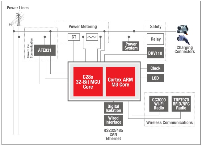
introduction As the proportion of electric vehicles on the road increases, so does the demand for charging stations. Although there are many charging stations available for free use in some restaurants and shopping centers, there is a growing demand for “paid charging stations†in urban and rural areas. These charging stations allow electric vehicles to travel longer distances. This requires higher technology for in-system communication, including Near Field Communication (NFC) technology for mobile payments, Wi-Fi, Ethernet and Power Line Communication (PLC) technology for payment processing, and the use of advanced meters And auxiliary control functions. With the advent of the C2000TM C28x Digital Signal Processor (DSP) + ARM® CortexTM-M3 devices, we can now integrate all of these features into a single, low-cost processor. Integrated communication Today, more and more people are using electric vehicles, whether they are motorcycles, special vehicles or public transportation on a daily basis. It has also led to an increase in the demand for charging stations, especially in helping these vehicles increase the distance traveled. Although charging is available in many locations, paid charging stations are also necessary. There are many charging stations in the city, which are similar in shape and working style to the parking meter, except that there is an additional charging line for connecting the electric vehicle. So far, there are three common charging stations (divided by level). Levels 1 and 2 are common "fuel gauge" AC Power Supplies that use the onboard charging function of an electric vehicle. Now, the third common charging station (not currently called a level) is the DC "quick charger", which bypasses the power factor correction (PFC) on the electric board and provides 400V DC power directly to the battery charging stage. All three systems have different power levels and power levels, but both need to measure how much power is used and explain the amount of charge to the consumer, while requiring communication with the back-end network. For credit card charging, mobile user charging, and even cash transaction processing, communication with multiple back-end networks is necessary. For designers, they need it to achieve the flexibility of their architecture. With TI's C2000 dual-core microcontrollers and other processors, we now have the flexibility of PLC, Wi-Fi, 10/100 Ethernet and NFC communication in a single processor. It also handles meter functions and housekeeping. Even power level control within the system. By integrating everything into a single controller, we can reduce board space, bill of materials costs, and integrate advanced protection features, all in one single controller. The advantages of real-time C2000 DSP+ARM The C2000 DSP+ARM family of microcontrollers, starting at just $7, is a new mixed-signal, multi-core processor device that belongs to the TI MCU family of devices. It combines the performance benefits of 32-bit processing with the C28x DSP core and combines the industry-standard ARM Cortex-M3 core flexibility to provide designers with unparalleled flexibility in mixed-signal, communication-based systems. Developers can also take advantage of the analog processing capabilities of these devices, with up to 24 ADC channels, 6 integrated analog comparators, and industry-standard communication protocols, including USB, 10/100 Ethernet, I2C, and SPI interfaces to Other radio technologies communicate to provide a complete system in one processor. Integrated memory, power supplies, and monitoring peripherals are also integrated into the device, further reducing the need for external components. Introduction to C2000 DSP + ARM Microcontroller: • Dual processor technology—independent C28x 32-bit control core and ARM Cortex-M3 communication core • Up to 1.5MB and 232KB of SRAM embedded flash for application memory and program memory • Integrated analog peripherals including 24 12-bit ADC channels, 6 analog comparators, and 27PWM output channels • Integrated communications including USB, 10/100 Ethernet, I2C, SPI and CAN peripherals • Single power operation • Integrated power-on reset and power-off reset function The basis of all meter systems does not exceed the analog processing capability of the main processing unit. With the analog capabilities of the C2000 dual-core device, we can easily implement the required voltage, as well as the current monitoring capabilities required for single-phase and three-phase AC measurements, and monitor the output levels of higher output DC systems. To simplify some of the diagrams in this article, we break the system into two subsections: 1. The monitored power supply itself 2. Low-voltage communication end of the system Since we are dealing with low pressure and high pressure systems, we must also consider the isolation requirements between high and low pressure systems. Although the C2000 dual-core device can handle power level control, this article focuses only on higher levels of measurement and communication. C2000 dual-core microcontroller for meter applications As mentioned earlier, electric vehicle chargers are currently divided into three categories: level 1 and level 2 represent AC charging, and level 3 is DC fast charging. In Level 1 and Level 2 systems, the charging station architecture appears to be very similar to the standard metering applications for most smart grid applications. This meter is simply connected to a single or three phase AC source (public grid) with no power control stage in the system. It works in exactly the same way as a household electric meter. It monitors the current through the system, only increases communication with the charging electric car, and as a payment gateway, it may also include a safe disconnect function. Both Class 1 and Class 2 chargers use an onboard charging system that includes a power factor correction boost stage and a high voltage DC charging circuit. The Class 1 charger is based on a standard 120/240V AC level and provides a maximum charge current of 16 amps. Level 2 charging can use 240V AC or 480V three-phase AC, but both are limited to 32A. In addition, in the case of level 1 or level 2, the charger acts only as a meter between the universal grid and the rechargeable electric vehicle, with no energy conversion stage. Figure 1 Simplified signal chain for “smart†fixed charging stations The DC Fast Charge System works in a different way, converting the AC supply voltage level to a boosted DC DC level that can deliver up to 400 amps of current. Although a Class 1 or Class 2 charger can charge a regular electric vehicle in 4 to 8 hours, the DC booster charger can perform the same charging work in 20 to 30 minutes. Class 1 and Class 2 power levels are very different compared to Class 3 chargers, but this metering application is common to all three chargers because the measurement input is always AC and is in front of all PFC stages. Inverters Converters,Inverter Ac Converters,Hybrid Inverter Converters,Frequency Inverters Converters GuangZhou HanFong New Energy Technology Co. , Ltd. , https://www.hfsolarenergy.com