Simulation of control algorithm for stepping motor of automobile instrument
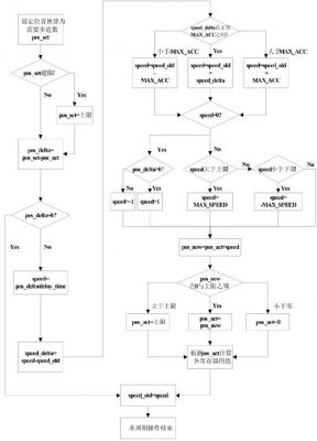
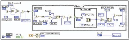
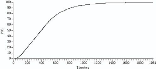
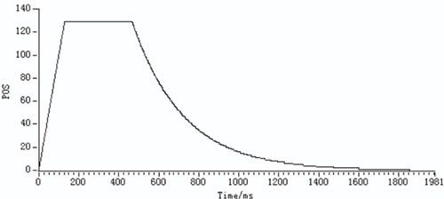
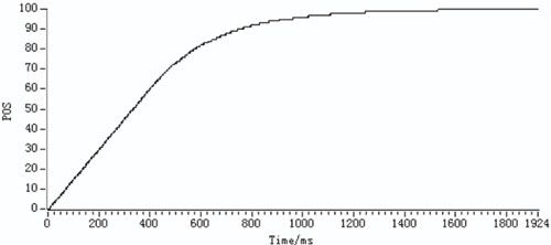
After experiencing the era of mechanical, electrical and analog electronic instruments, automotive instrumentation has entered the era of all-digital instrumentation of stepper motors. At present, some domestic medium and high-end cars are equipped with stepper motor vehicle instruments. Other cars are also supporting this type of instrument. Stepper motor vehicle instrumentation will be the leading product of automotive instrumentation in the future, with a very broad market prospect. This article refers to the address: http:// In the future, the functions of automotive instrumentation will be more focused on software. This has special significance for automotive instruments that have a large number of products and are extremely cost sensitive. Compared with automobile instruments consisting only of electronic hardware, the realization of the vehicle instrument function with ECU is more flexible and diverse, and the product's “flexibility†is better, that is, when the new product is introduced, the softness of the previous product can be utilized to the utmost. Hardware design results, which are particularly important today and in the future when product updates are fast. At present, many semiconductor chip manufacturers produce microcontrollers for automotive instrument panels, such as NEC, freescale, Fujitsu and Micronas. Here is a solution for stepping motor control of automotive dashboard based on Micronas CDC3207G microcontroller. Stepper motor control The stepping motor, also known as the pulse motor, can turn the input pulse signal into a stepping rotation of the motor shaft, which is an actuator that converts the electric pulse into an angular displacement. In the case of non-overload, the speed of the motor and the position of the stop depend only on the frequency of the pulse signal and the number of pulses, and are not affected by the load change. Controlling the stepper motor actually controls the input pulse sequence to rotate the stepper motor shaft in the desired direction. The main application in automotive instrumentation is a two-phase stepper motor with two independent windings. The control of the stepper motor can be achieved by controlling the pulse signals on the two separate windings. In addition, the inside of the stepping motor is equipped with a speed reduction gear set between the motor shaft and the pointer, so that there is a certain speed reduction ratio between the rotating shaft and the pointer, which can reduce the shaking of the pointer rotation and make the motor pointer rotate more smoothly. . The control algorithm adopts the SWITEC stepping motor of Microcomponents Company. The speed ratio between the rotating shaft of the motor and the pointer is 180:1, that is, the rotating shaft of the stepping motor rotates by 180°, and the pointer of the stepping motor rotates by 1°. Stepper motor control algorithm Basic function of control algorithm The main function of the control algorithm is to control the stepping motor to complete the display of the instrument. The main purpose is to calculate the position information of the display instrument based on the real-time data, and then calculate the stepper motor control command according to the position information. For the microcontroller integrated with the stepper motor control module, the control algorithm finally outputs the value of the control register, and the microcontroller generates a drive signal according to the value of the register to realize the control of the stepping motor. CDC3207G microcontroller The CDC3207G microcontroller is a 32-bit [0] microcontroller based on the ARM7TDMI core from Micronas. It integrates 7 stepper motor modules, plus PWM software simulation can directly drive up to 8 steps. Enter the motor. Each stepper motor module directly drives the two-phase stepping motor by connecting the high-current output port of the H-bridge internally to the four controllers. Various pulses required for stepper motor positioning can be generated by software. The CDC3207G's stepper motor module provides multi-channel PWM output. The output signal frequency is selected by hardware settings, and the timing of each stepper motor module output signal is offset to improve electromagnetic compatibility (EMC). According to the needs of controlling two-phase stepper motors, the CDC3207G internally provides three 8-bit registers for generating control pulses via software. Two of the registers are compared to the module timer by a comparator in the module to generate the PWM signal for driving the motor, and another register is used to select the corresponding stepper motor module and select the polarity of the four output pins. In this way, each stepper motor can be conveniently controlled by software operation of three registers. In addition, the CDC3207G also has a zero detection function, that is, detecting the induced current when the motor is running, and obtaining the position information of the motor running, thereby judging whether the motor reaches the initial position (ie, the zero position of the automobile meter). Implementation of control algorithm The main task of the software is to calculate the value of the control register based on the updated stepper motor position information. At the same time, in order to meet the real-time requirements of the instrument indication, this solution adopts the method of periodically calling the stepper motor control function to select the cycle according to actual needs. In this solution, the cycle of calling the stepper motor control function is 2ms. In addition to the need to meet real-time performance, the stepper motor control function also needs to control the stepper motor to operate smoothly, so that the display of the pointer does not visually give people an uncomfortable feeling. To this end, the control function needs to limit the speed and acceleration of the stepper motor. Since the stepper motor position information is periodically updated, the control function calculates the step amount per cycle by comparing the current position with the given position, and finally completes the display of the given position. The control function flow chart is shown in Figure 1. Figure 1 Stepper motor control function flow chart The SWITEC stepper motor of this scheme has a pointer display range of 330°. For every degree of rotation of the pointer, the stepping motor rotation axis needs to be rotated by 180°, which is divided into 256 steps in the software. Therefore, the stepping motor range calculated according to the number of steps is 330 × 256 = 84,480 steps. In order to ensure that the pointer display is smooth and smooth, it is necessary to limit the maximum number of steps in each cycle and the difference in the number of steps between two adjacent cycles. The constants MAX_SPEED and MAX_ACC respectively limit the motor running speed and acceleration. Since the position of the stepping motor needs to be updated periodically, and the cycle time is short and the number of steps is limited, for a new meter position, the stepping motor often needs multiple cycles to complete the display. A brief description of some of the variables is given in Table 1. Table 1 variable description Variable name Pos_set Pos_act Pos_new Delay_time Speed Speed_old meaning target address current location End of this week Response time Weekly step number Upper cycle step number Since the position information in the program is represented by the number of steps, a constant array can be defined in advance, and the value of the control register corresponding to the number of steps is saved. In this way, the value of the required register can be obtained by stepping through the table as needed. Control algorithm analysis In order to further analyze the performance of the algorithm, the LabVIEW programming software is used to simulate the algorithm, so that the algorithm can be easily analyzed without connecting the stepper motor. The algorithm can be analyzed in LabVIEW 7.1 using the block diagram of Figure 2. Figure 2 LabVIEW algorithm block diagram In LabVIEW, a while structure is used to periodically process the target address of the algorithm. Each cycle gets the value of pos_new, which is the display value of the stepper motor after each cycle, and then outputs the value to the front panel of LabVIEW. on. The front panel is shown in Figure 3. Figure 3 LabVIEW algorithm front panel The start and end of the cycle can be controlled by the Start button in the front panel, and the value of pos_set can be manually changed to simulate the data change in the actual meter. In this case, the value varies from 0 to 100, and the value is mutated from 0 to 100 for each test. Using Gauge (gauge) to simulate the display of the stepper motor, it is convenient to observe the visual effect displayed after the different parameters are changed. In addition, you can use the drawing function provided by LabVIEW to obtain images of some important variables in the algorithm over time, and perform performance analysis more intuitively. Figure 4 pos_new changes over time Fig. 4 is a graph showing the actual output value pos_new of the stepping motor as a function of time in the process of the stepping motor target value pos_set being abrupt from 0 to 100. Since the set while cycle is 1ms, the time axis shows the stepper motor output per cycle, and the ordinate POS is the display result of the stepper motor. Observing the curve from 0 to 128ms, it can be seen that the slope of the curve is gradually increased, indicating that the stepper motor is running at an accelerated speed because the difference between the target position and the actual position of the stepping motor in the initial stage is large. The speed_delta value exceeds the limit of the MAX_ACC constant. The curve from 128ms to 475ms is a straight line, indicating that the stepper motor has reached the maximum speed MAX_SPEED in this interval and runs at this speed at a constant speed. For the curve of the remaining interval, the slope is gradually reduced. At this time, the stepping motor is running at a reduced speed because the difference between the target position and the actual position is already small, and the calculated speed_delta value is already within the range limited by MAX_ACC. The three curves of the variable speed over time can more clearly distinguish the three processes. As shown in Figure 5. Figure 5 speed changes with time The constant MAX_ACC (ie, the change in the number of steps in the adjacent cycle) is changed from 1 to 10, and the simulation results are shown in Fig. 6. It can be seen that after the MAX_ACC is increased, the initial stage of the curve becomes steeper, that is, the acceleration of the stepping motor in the initial stage becomes faster, and the stepping motor is less affected by the initial value of 0 to 100. . Figure 6 pos_new changes over time after changing MAX_ACC It is not difficult to see from the flow chart that the constant MAX_ACC only limits the change of the number of steps in the adjacent two cycles, and the limit of the number of steps per cycle is set by MAX_SPEED. Changing the value from the original 128 to 256 and the same test can be found that the curve becomes steeper between 200ms and 400ms, and the stepping motor is shortened from 0 to 100. This shows that the stepper motor completion time can be significantly changed by changing the limit of the number of steps per cycle. Of course, the final display results and the results of the simulation will be biased due to the performance of the stepper motor itself, and the actual stepper motor will have problems such as noise that cannot be simulated by LabVIEW. Therefore, the algorithm simulation using LabVIEW can only be used as a reference. The final parameter determination needs to be completed after testing on the actual stepper motor. Conclusion For this control scheme, the design developer can change the range and indication of the stepper motor indication according to the actual hardware (such as the stepper motor model) and the needs of the instrument product, and modify the constant values ​​of the upper and lower limits of the corresponding variables in the program. A sequence of indicators such as smoothness and response speed. It is very convenient to modify and debug. Although this scheme is designed for the CDC3207G microcontroller, the control algorithm idea in software design has universal applicability for the control of stepping motor of automobile instrument. India Modular Wall Switch And Socket India Modular Wall Switch And Socket,India Modular Wall Switch,India Modular Wall Socket,Best India Modular Wall Switch ZHEJIANG HUAYAN ELECTRIC CO.,LTD , https://www.huayanelectric.com