Design of home appliance gateway using Zigbee technology and embedded system
Aiming at the requirements of modern society for information access convenience and home networking, a home gateway that can organize household appliances into a small network is designed. The gateway adopts the design scheme of the combination of Zigbee technology and embedded system, and adopts the self-designed Zigbee protocol stack structure to make it suitable for embedded systems and achieve the ability to connect networking and exchange information. 0 Introduction The gateway may be familiar to people who have used the Internet, such as a router connecting a personal computer and the Internet in your home or office. The gateway discussed here, its role is not to connect your personal computer to the Internet, but to connect the large and small household appliances in your home to your personal computer, and then you can go through the PC without going into your home. Control home gateways to get home appliance information and control them. Because it uses Zigbee wireless technology, it is also called a home wireless gateway. 1 The architecture and topology of Zigbee technology In Zigbee technology, its architecture is usually to quantify its various simplified standards through "layers", and each layer is responsible for completing the tasks specified for it and providing services to the upper layer. The architecture of Zigbee technology is mainly composed of physical (PHY) layer, media access control (MAC) layer, network / security layer and application framework layer from bottom to top. 2 Home gateway structure and its hardware and software composition Combining the master-slave relationship between home gateway and home appliances in this topic, this paper uses a Zigbee network based on star topology. Because the Zigbee wireless gateway needs to forward the information based on the TCP protocol to other nodes in the Zigbee network, it must be an FFD device, and it must also manage some information of other nodes in the entire Zigbee network. . 3 The specific operation process of the home gateway and its pseudocode Zigbee protocol stack and TCP / IP protocol stack are respectively two tasks of the uCOS-II system. Data communication between the two tasks is carried out in the form of message queue or mailbox. To achieve the task of data exchange. 4 Gateway debugging method Specific operation process: 5 Conclusion Through the design and analysis of the gateway, the gateway is found to be practical and feasible. During the design of the gateway, many difficulties were encountered. For example, there is currently no Zigbee protocol stack for the ARM platform. Only existing Zigbee protocol stacks can be modified and transplanted to suit the ARM platform. This step is achieved It's more complicated. In addition, in order to save equipment costs, two RFD devices are connected to a Zigbee wireless gateway device at the same time during the test, and the distance is relatively short, which is not applicable in actual production testing. REMOTE CONTROL SOCKET
Programming Instructions
•Press any ON switch on the Remote Control for approximately 2 seconds and the Remote Socket(s) learn the code. The LED will stop flashing top confirm the codehas been accepted. remote switch,remote plug,remote control switch,remote power switch,remote control sockets NINGBO COWELL ELECTRONICS & TECHNOLOGY CO., LTD , https://www.cowellsocket.com
Keywords: home gateway; Zigbee; TCP / IP; serial port debugging 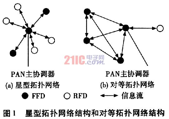
The Zigbee technology network has two kinds of topologies: star topology and peer-to-peer topology (as shown in Figure 1). Two types of devices are defined: full-function devices (FFD) and reduced-function devices (RFD). FFD is relatively complete in hardware function, and can communicate with all other FFD or RFD, and RFD can only communicate with the FFD associated with it. The FFD device associated with the RFD is called the "coordinator" of the RFD. In the entire network, there is an FFD that acts as a network coordinator. In addition to participating directly in the application, the network coordinator also needs to complete tasks such as membership management, link state information management, and packet forwarding. 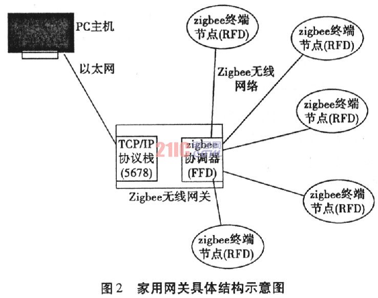 According to the requirements of the subject, the selected system hardware composition: using S3C4480 embedded development board, the development comes with 2M FLASH and 8M RAM. The network chip uses the RTL8019 10M network chip, and the Zigbee communication module uses TI's CC2420 chip (two pieces).
The selected system software is composed of: uCOS-â…¡ + basic function Zigbee protocol stack + LWIP TCP / IP protocol stack.
The basic function of the Zigbee wireless gateway is to convert the network based on the TCP protocol and the data based on the Zigbee protocol stack, so that the data based on commonly used Ethernet can be sent to the Zigbee network, or the data in the Zigbee network can be sent to the Ethernet. in. Turn on the Zigbee wireless gateway, and other RFD nodes communicate with it to join the wireless network. In this way, Zigbee wireless gateway can manage all nodes.
There are two main protocol stacks involved here: Zigbee protocol stack and TCP / IP protocol stack.
TCE / IP protocol stack Choose the LWIP protocol stack suitable for embedded applications here, which has good portability and open source code.
Considering that there is currently no fully usable Zigbee protocol stack, a basic function Zigbee protocol stack is defined and implemented here. The basic structure is:
(1) phy layer: This layer mainly implements operations related to specific Zigbee module hardware.
(2) Mac layer: Based on the interface provided by the phy layer, the basic initialization of the Zigbee network is realized, the PAID is set, the IEEE 64-bit address is set, the communication channel is selected, and the function of receiving and sending Zigbee data packets is realized.
(3) nwk layer: This part is used to obtain the received data from the mac, analyze the data, and perform a series of operations. According to the data sent, if it is the data of the application layer, the received data is passed up. If it is a network layer command, then perform specific operations.
The network layer commands implemented are:
a) The terminal node (RFD) requests to join the network: verify and assign an address to the joining terminal node.
b) The terminal node (RFD) requests to leave the network: verify and delete the node from the node information list.
c) The terminal node (RFD) successfully joined the network.
d) The terminal node (RFD) successfully leaves the network.
In addition, it includes FFD response commands for these requests.
(4) App layer: This layer obtains data from the nwk layer and operates according to the data content, which is related to specific applications.
When starting the host software, the user uses the connection of the Zigbee gateway by setting the IP of the Zigbee gateway to be connected. After the connection is successful, the PC host requests information about all nodes in the Zigbee network. The Zigbee gateway sends all node information in the Zigbee network to the host, and the host software displays all possible nodes. After obtaining all the node information, the user can select the node to be communicated, and send all the operation information to the node through TCP, so as to control and monitor the node.
Here the pseudo-code for the basic process of the Zigbee protocol stack task is written. 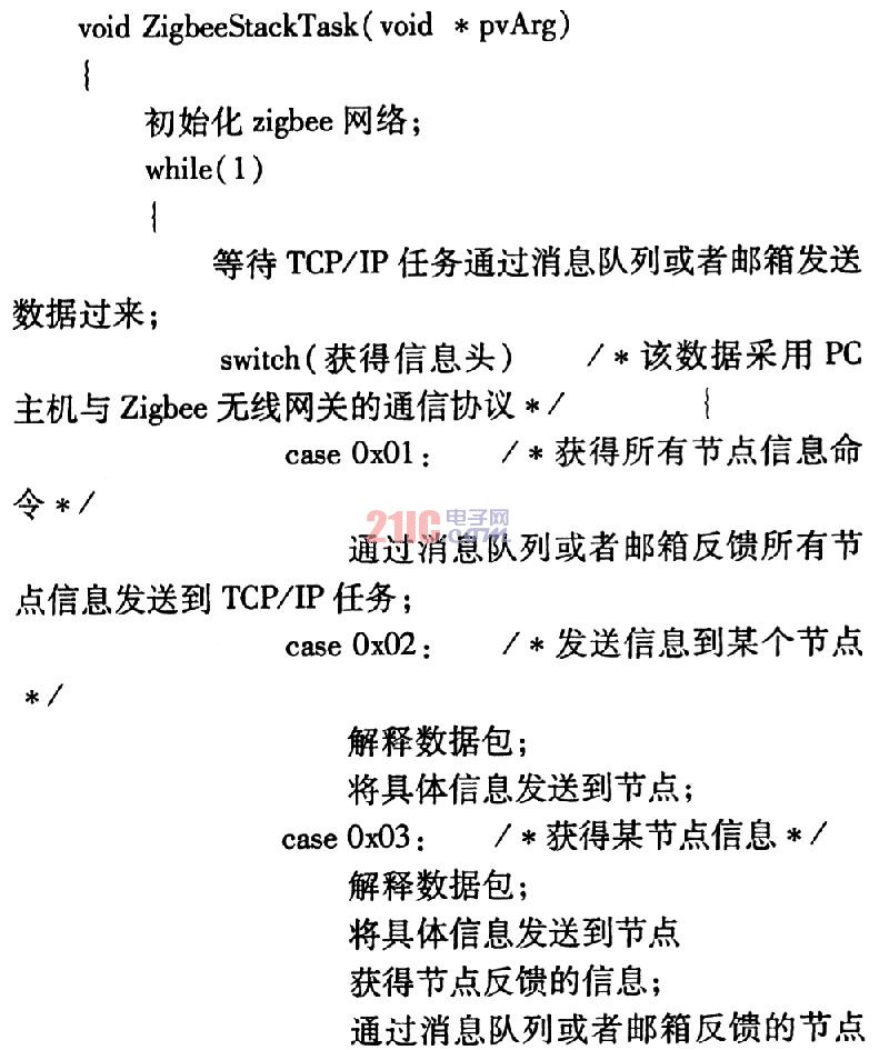
(1) Open the serial debugging assistant software, set the baud rate to 57 600, 8 bits, 1 bit stop, no parity and flow control protocol.
(2) Connect the serial port of Zigbee and PC, and connect the power supply at the same time.
(3) Information about device startup and Zigbee gateway related information will be displayed in the serial debugging assistant software. This shows that the Zigbee network has been initialized and formed a Zigbee network.
(4) Open the host software, set the IP address of the connected gateway, and then click the "Connect" button. At this time, all the Zigbee node information is displayed in the list box on the left side of the software. You can also obtain it by "Refresh node information" below The latest node information list.
The read-only edit box at the bottom of the host software displays some log information, which is convenient for debugging. Figure 3 shows the commissioning of the gateway:
Important Safeguards
When using any electrical appliance, in order to reduce the risk of fire, electric shock and/or injury to persons, basic safety precautions should always be follow8d. including:
• The appliance is for household and indoor use only.
• Before plugging in. check that the voitage on the rating label is the same as the mains supply.
• To protect against electric shock, do not immerse any part of the product in water or other liquid.
• This socket is intended for use by competent adults only and children should be supervised at all times.
• Do not use the socket for other than its intended use.
• This socket can be used by children aged from 8 years arxl above and persons with reduced physical, sensory or mental capabilities or lack of experience and knowledge if they have been given supervision or instruction concerning use of the appliance in a safe way and understand the hazards involved. Children shall not p<ay with the appliance Cleaning and user maintenance shall M be made by children without supervision.
• Children of less than 3 years should be kept away unless continuously supervised.
Children from 3 years and less than 8 years shall only switch on/off the appliance provided that it has been placed or installed in its intended normal operating position and they have been supervision or instruction concerning use of the appliance in a safe way and understand the hazards involved. Children aged from 3 years and less than 8 years shall not plug in. regulate and clean the appliance or perform user maintenance.
• Don't use this socket in the immediate surroundings of a bath, a shower or a swimming pool.
• In case of malfunction, do not try to repair the socket yourself, it may result in a fire hazard or electric shock
Do Not Exceed Maximum a680W
Place the LR44 batteries provided into the compartment in the back of the Remote Control, please insert as sho*/m in the back of the compartment to ensure the polarity is correct.
• Plug the Remoce Socket$($)lnto the wall socket(s) and switch on the mams supply, the red LED will flash every second.
• If the LED is not flashing press & hold the manual ON/OFF button for 5 seconds until it Hashes
• Any number of Remote Sockets can be programmed to one Remote Control ON button to create multiple switching.
• To programme o<her Remote Sockets on different Remote Control ON buttons repeat the prevous steps
• If the mains supply is turned off the Remote Sockets v/ill lose their code and it wil be necessary to re-pcogramme.
Operation:
• Plug your appliance(s) into the Remote Socket(s)
• Press the programmed ON or OFF button on the Remote Control to control the Remote Socket.
♦ The Remote Sockets can also be operated manually using its ON/OFF Button Trouble shooting
If a Remote Socket does not react to the Remote Control please check the followng:
♦ Low battery in tbo Remote Control
• Distance too large between the remote control and the recerver (ensure the range distance is no more than 20 clear Metres) and free from obstacle that may reduce the distance.
• If programming has not been successful, tum the power off and back on then follow the programming steps above.
How to decode
• Press the manual ONX)FF button for 5 seconds until the red LED flashes once per
second to confirm de-coding is successful
♦ Press the ALL OFF switch on the Remote Control for more than 3 seconds, the LED
flashes once per second to confirm (decoding successful.
Voltage: 240V-/50HZ
Max power rating: 3680W max.
Remote frequency:
Remote range:
Battery Type:
433.92MHz
230 Metres
Button Cell 2x1.5V LR44 =
Please check with your local waste management service authority regarding regulations for the safe disposal of the batteries. The batteries should never be placed G municipal waste.
Use a battery d^posal facility if available
M
For eioctncal products sold within the European Community. At the end of the electrical products useful life, it should not be disposed of wth household waste. Please recycle faaMies exist. Check with your Local Authonty or retailer for recycling advice.
C€