Wireless mouse system circuit design plan Daquan (three circuit design principles in detail)
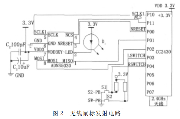
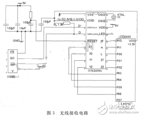
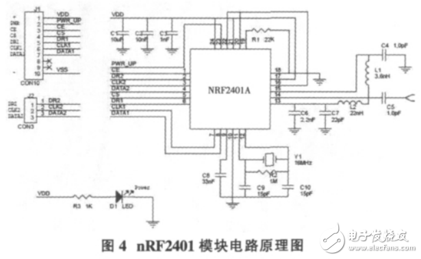
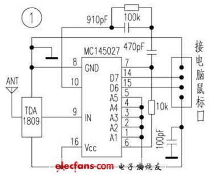
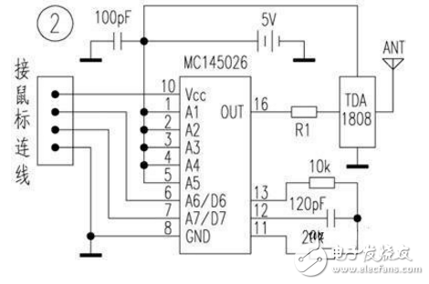
The designed wireless mouse uses CC2430 as the control chip to form the transmitting circuit and the receiving circuit. The transmitting circuit is responsible for collecting and transmitting mobile information of the mouse button, and the receiving circuit is responsible for receiving, processing, and communicating with the computer. The hardware circuit of the transmitting part is composed of a mouse moving optical sensor ADNS5030, a mouse button, and a wireless transmitting module CC2430 (software set to a transmitting mode). The movement information of the mouse is detected by the optical sensor ADNS5030, and the collected information is transmitted to the CC2430 through the SPI serial interface for processing and transmission. The circuit diagram of the transmitting part is shown in Figure 2. The ADNS-5030 optical sensor features low power consumption and small size for high-speed detection of mouse motion. It includes an image acquisition system (IAS), a digital signal processor (DSP), and a serial bus port. The IAS processes the acquired image through digital signals, calculates the relative displacement of the mouse in the dx and dy directions, and determines the direction and distance of the movement. The wireless mouse uses a mechanical push button switch. The design of the left, right and wheel button circuits is shown in Figure 2. These buttons are directly connected to the I/O port of the wireless module CC2430. Pressed as digital signal "0", not as digital signal "1". These buttons complete the click, double click, and drag operations. The receiving circuit is composed of a USB interface control chip HT82M98A and CC2430 (set to receive mode). The receiving part communicates with the computer through the USB interface chip HT82M98. The power of the HT82M98A is provided by the USB interface. The power supply of the wireless module CC2430 is powered by 3.3V from one pin of the HT82M98A. After receiving the data packet, the CC2430 decodes it and transmits it to the HT82M98A through the I/O port status, and transmits it to the computer via USB. The receiving circuit is shown in Figure 3. Figure 3 wireless receiving circuit mouse controller HT82M98A has an on-chip USB interface, built-in HID class USB mouse protocol. There is no need to install a dedicated driver on the computer, and the Windows operating system will automatically recognize the interface control chip HT82M98A. The main body of the system work is the 51 series MCU, which transmits and accepts two parts. The transmitting part is mainly composed of a touch detection screen, a MEMS acceleration sensor, an MCU and an nRF2401 transmitting module, and the main function is to realize collection and transmission of gesture movement trend information. The touch screen is used to detect the change of the coordinates X and Y during use, and the simulation of the movement trend of the mouse is completed by analyzing the trend of X and Y changes. Since the chip integrates all the high-speed signal processing parts related to the RF protocol, such as the SPI interface inside the nRF24L01, it can be simulated by the hardware SPI interface or I/O port of the microcontroller. Secondly, the link layer is fully integrated in the module, very Easy to develop. Figure 4 shows the circuit schematic of the nRF2401. The principle circuit is shown in the figure. By outputting different voltage changes to its 3-axis output, it can be used to perceive people's actions in different directions during use, such as waving, swinging arms, etc., and then different actions can be defined as special functions, such as PPT when implementing speech. , PDF page turning, closing the window, switching windows and other actions. This design utilizes the codec circuit MC145026/MC145027 and the RF transmit/receive module TDA1808/TDA1809 to cooperate with each other, and can flexibly manipulate the mouse within the range of 10 to 120m, and does not need to make any changes to the appearance and internal circuit of the original mouse during use. It fits the operating habits, is convenient and reliable, and is very suitable for lovers to make. Under normal circumstances, there are 4 circuit cables inside the connection line between the mouse and the computer (the circuit device can accept up to 4 data lines input, the reader can choose according to the actual situation of the mouse): the positive power supply, the power supply ground, and the data cable. 1. Data line 2. We cut the mouse connection and find the four lines separately. The data transmission terminals D6 and D7 of the MC145026 encoding circuit accept the data transmitted from the mouse data line 1 and the data line 2, and are internally coded by the RF transmitting module. The TDA1808 is launched. After the RF transmitting module TDA1809 is working, the received encoding information is input into the MC145027 decoding circuit, and after the conversion, the signals of the original mouse data line 1 and the data line 2 are restored at the data output terminals D6 and D7 of the chip, and the original mouse is used. The computer cable is sent to the computer. It can be seen that the above circuit does not need to change the mouse and the computer, and it is not necessary to install additional mouse driver software, and all the functions of the original mouse can be used normally. This circuit (see Figure 1, Figure 2) works as long as the selected component is normal and does not require commissioning. Insulated Terminals,Terminals,High-quality insulated terminals Taixing Longyi Terminals Co.,Ltd. , https://www.lycopperlugs.com