25W x with LM1875 and 2SA1943 / 2SC5200
The circuit is shown in Figure 1. The chip IC uses the LM1875 of the American NS company. It has a soft tone and low distortion (0.015%). It is quite famous at low power and is widely praised. The output tube adopts the relatively warm and soft Toshiba high-power pair tube 2SA1943, 2SC5200 (VCM = 180V, ICM = 12A, PCM≥120W, fT = 30MHz). The principle of this circuit is as follows: when the audio signal is input to the positive phase input terminal of IC through C1 and R1, the voltage of the power supply resistors R4 and R5 connected to the positive and negative power supply of the IC will change with the signal. R5 is the bias resistance of the power tube. When the signal reaches the required amplitude, the power tubes VT1 and VT2 are turned on, so that the power of the LM1875 is expanded. When using ± 25V power supply, the output power can reach more than 30W under 8Ω load. Follow WeChat Download Audiophile APP Follow the audiophile class related suggestion Avago Introduces New High Linear Power Amplifier Module Product Avago Technologies ... The word "Monster" has both positive meaning and ... When the output power of the digital power amplifier is greater than 50W, it is impossible to use only ... If an "audiophile" is a group of people who are never satisfied with the sound and "loved the new and the old" with the audio equipment. Then just rely on these so-called "fever spirits" ... First, the circuit principle and characteristics 1. Power amplifier part (see Figure 1) There is a well-known saying in the Hi-Fi world that is "briefness first." This means that if ... Simple and practical TDA2822M integrated power TDA2030 is ... STK465 thick film ... This RF power amplifier can output 2-3 channel signals, covering an area of ​​about one square kilometer, is ... Low frequency power amplifier Looking at the Hi-Fi amplifiers currently on the market, the output power is 100W ... With the newly launched LM4651 and LM465 from National Semiconductor ... EL34 (6CA7) was first launched by Philips in 1956 ... This article cleverly combines the electronic tube EL34 and the transistor (op amp), ... The pre-amplifier adopts a European-made TESLA brand low noise high cheek double transistor ... "Simple" means the circuit of the amplifier is simple, making it easier, as long as the picture ... 1. Description: & nb ... The Class A transistor power amplifier has a warm and sweet tone, which makes people tempted. But the temperature rise of Class A amplifier ... The circuit is shown in Figure 5, ... '+ data.data.username +' '; dom + =' GALOCE Shear beam Load Cell, cantilever load cell also called single ended shear load cell, bending beam load cell, tend to be the most commonly used due to the variety of available options. load cell 1ton,500kg load cell,3 ton load cell are hot sales still. A beam load cell is one of the major categories or types of load cell commonly found within the weighing industry. Other types include, for example; compression, tension and single-point. They are arguably the most common type of load cell in use today.One end of the shear beam load cell contains the mounting holes while the opposite end is where the cell is loaded. The load cell should be mounted on a flat smooth surface with high strength hardened bolts. The larger shear beam cells have more than two mounting holes to accommodate extra bolts to keep the hardware from stretching under stress load. They are widely used in floor scale, livestock scale, anilmal scale, forklift scale, tank weighing systems and other weighing devices. Shear Beam Load Cell,Beam Load Cells,single ended shear load cell,3 ton load cell,500kg load cell GALOCE (XI'AN) M&C TECHNOLOGY CO., LTD. , https://www.galoce-meas.com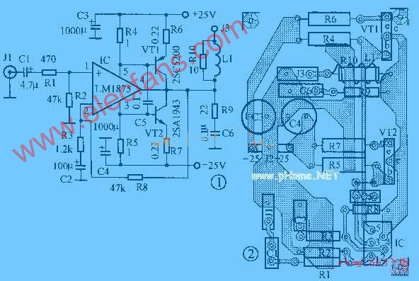
The printed board diagram is shown in Figure 2 (two channels are required for two channels). Assembly points: Because the negative power supply of the IC is connected to the metal cap, an insulation sheet and a sufficient amount of silicone grease must be added between the IC and the heat sink The heat sink should be genuine and should not be hot during long hours of work, otherwise the heat sink should be increased. Since the quiescent current of the IC is about 70mA, the values ​​of R4 and R5 determine the conduction point of the power tube. In this circuit, when the IC output current is close to 1A, the power tube is turned on. R4 and R5 use a 3W non-inductive resistor. Imported genuine power tubes are selected and matched, and the error is as small as possible (within 3%), which is especially important for the clarity of music. The coil L1 at the output end is densely wound 10 turns on the 3W non-inductive winding resistor R10 with φlmm enameled wire. The power supply part (see Figure 3 and Figure 4) uses 150W dual 18V high-quality toroidal transformer, 4 filter capacitors of 35V / 4700μF, two 35V / 100μF, two 100V / 0.1μF, and 4A fuse tubes FUSE1 and FUSE2. 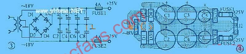


![[Photo] 15w RF power amplifier](http://i.bosscdn.com/blog/20/06/41/521040781.gif)
![[Photo] Broadband high frequency power amplifier](http://i.bosscdn.com/blog/20/06/41/520536801.jpg)
![[Photo] TDA2030 audio power amplifier](http://i.bosscdn.com/blog/20/06/41/5131012891.gif)
![[Photo] Transistor 15W Class A Power Amplifier](http://i.bosscdn.com/blog/20/06/41/513102891.gif)
![[Photo] 125W Class D Subwoofer Power Amplifier](http://i.bosscdn.com/blog/20/06/41/513100868.jpg)
![[Photo] Mark Levinson No. 30 ...](http://i.bosscdn.com/blog/20/06/41/513544752.jpg)
![[Photo] 45W transistor tube hybrid power amplifier](http://i.bosscdn.com/blog/20/06/41/513531952.jpg)
![[Photo] 32W hybrid audio power amplifier](http://i.bosscdn.com/blog/20/06/41/513526493.jpg)
![[Photo] Gallstone hybrid power amplifier using switching power supply](http://i.bosscdn.com/blog/20/06/41/513524776.gif)
![[Photo] Simple fool power amplifier](http://i.bosscdn.com/blog/20/06/41/513432946.jpg)
![[Photo] LM386 low voltage audio power amplifier ...](http://i.bosscdn.com/blog/20/06/41/513417261.gif)
![[Photo] Class A power amplifier using SAP15N / P audio pair tube ...](http://i.bosscdn.com/blog/20/06/41/513346769.gif)
![[Photo] Using TDA7294 and 2SA1216 / 2S ...](http://i.bosscdn.com/blog/20/06/41/4233420295.gif)
'+ data.username +'
'+ data.username +'
'; dom + ='
'; $ (' # follow_list '). append (follow_user);} if (data.status == "failed") {alert (data.msg);}});} else {// Unfollow if ($ ( this) .attr ('id') == 'cancelFollow') {$ .post ('/ d / user / cancelFollow', {tuid: article_user_id}, function (data) {// Data format returned: if (data .status == "successed") {follow_wrap.html ('Follow'). attr ('id', 'follow'). css ('background', '# f90'); $ (". followNum strong"). html (-getFollowNum); $ ('# follow_list .face'). each (function () {var target_uid = $ (this) .attr ('data-uid'); if (target_uid == now_uid) {$ ( this) .remove ();}})} if (data.status == "failed") {alert (data.msg);}}); return false;}}});});}); / * var myface = "{$ _super ['uid'] | avatar}"; var myname = "{$ _super ['username']}"; var article_id = {$ article ['id']}; var article_user_id = {$ article ['mid']}; // Article author ID $ (function () {<notempty name = "clearnum"> // Reduce the number of reminders var count = parseInt ($ ("# noticeCount"). html ()); count = count-{$ clearnum}; $ ("# noticeCount"). html (count); if ( count