Mitsubishi PLC serial communication development experience
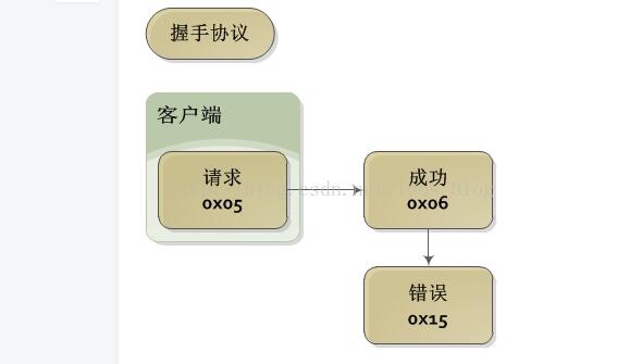
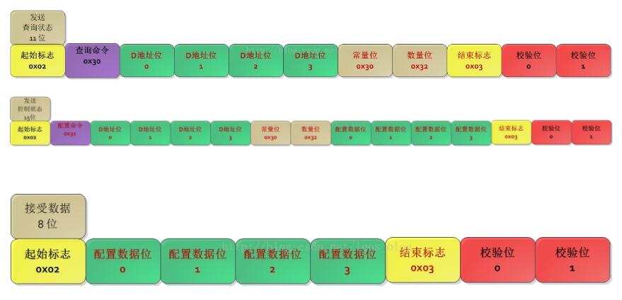
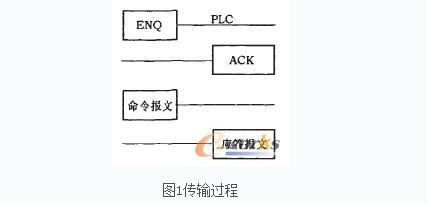
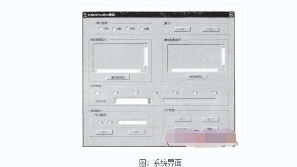
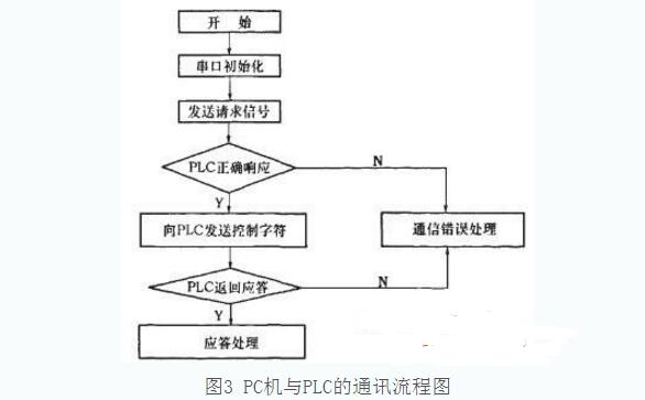
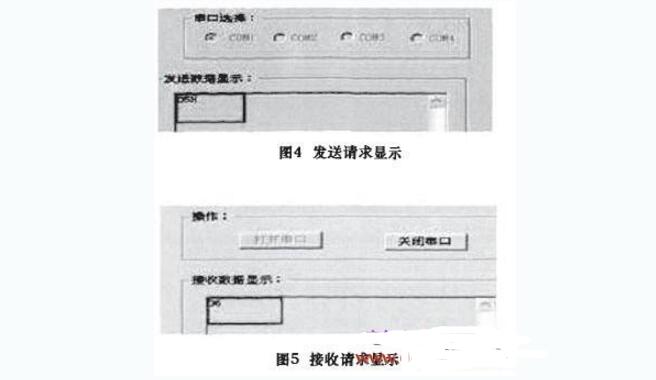
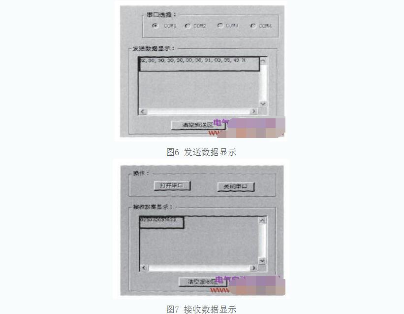
Serial communication and parallel communication are two different data transmission methods. Serial communication is to connect the sender and the receiver through a pair of wires. Each bit of data is transmitted and received on the same wire in a specified order. For example, the commonly used USB USB interface is serial communication. The characteristic of serial communication is that the communication control is complicated and there are few communication cables. Therefore, compared with parallel communication, the cost is low. Parallel communication means that each bit of an 8-bit data (or 16-bit, 32-bit) is transmitted on a separate wire, and the transmitting and receiving sides are connected in parallel. Each bit of a data can be at the same time. One transfer. For example, the communication between the printer port of the old printer and the computer is parallel communication. The characteristic of parallel communication is that it can transmit multiple bits of data at a time in one cycle, and it has many cables for connection, so it is costly to transmit over long distances. I remember that when I first started working on software development two years ago, my first task was to develop a program that could implement serial communication with Mitsubishi PLC. The so-called communication, the essence of which is mainly to PLC D register (dword) read and write operations. However, because Japan protects its products, it does not develop serial communication protocols. In the case of not developing a communication protocol, if you want to implement communication, the first thing you need to do is to analyze the data and crack the communication protocol. Here is not to explain how to crack, mainly to introduce the background of the blogger development program at that time. The main purpose of writing this article is to share your own development experience in the past, because you have received a lot of open source software in the process of development, and now it is transferred to the topic. Involving byte-stream data communications necessarily involves communication protocols. Given the development needs at the time, bloggers only analyzed the read and write protocol of the D register. Other registers are theoretically similar, and interested students can analyze the data for testing. D register communication protocol is relatively simple, can be divided into: 1. Greeting response protocol 2. Status query protocol 3. State Configuration Protocol 4. Data feedback protocol The three main difficulties in PLC communication are the encryption and decryption of registers, the encryption and decryption of data information, and the verification of characters. "span style="font-size:18px;""void PLC_dataparse::Encrypt_toPLCaddress( BYTE *parray , const UINT paddress ) { Int encode_address = 0x1000 + paddress * 2; BYTE encrypt_key = encode_address & 0xf; Parray[3] = (encrypt_key10) ? (encrypt_key + 0x30) : (encrypt_key + 0x41 - 0xa); Encrypt_key = (encode_address )" 4) & 0xf; Parray[2] = (encrypt_key10) ? (encrypt_key + 0x30) : (encrypt_key + 0x41 - 0xa); Encrypt_key = (encode_address )" 8) & 0xf; Parray[1] = (encrypt_key10) ? (encrypt_key + 0x30) : (encrypt_key + 0x41 - 0xa); Encrypt_key = (encode_address )" 12) & 0xf; Parray[0] = (encrypt_key10) ? (encrypt_key + 0x30) : (encrypt_key + 0x41 - 0xa); } "/span" "span style="font-size:18px;""void PLC_dataparse::Encrypt_toPLCcontent( BYTE * parray , const UINT pcontent ) { BYTE encrypt_key = pcontent & 0xf; Parray[1] = (encrypt_key10) ? (encrypt_key + 0x30) : (encrypt_key + 0x41 - 0xa); Encrypt_key = (pcontent )" 4) & 0xf; Parray[0] = (encrypt_key10) ? (encrypt_key + 0x30) : (encrypt_key + 0x41 - 0xa); Encrypt_key = (pcontent )" 8) & 0xf; Parray[3] = (encrypt_key10) ? (encrypt_key + 0x30) : (encrypt_key + 0x41 - 0xa); Encrypt_key = (pcontent )" 12) & 0xf; Parray[2] = (encrypt_key10) ? (encrypt_key + 0x30) : (encrypt_key + 0x41 - 0xa); } "/span" "span style="font-size:18px;""void PLC_dataparse::Add_checkcode( BYTE * pdest, BYTE * psrc, const UINT plenth ) { Int sumtemp = 0; For (unsigned int i = 0; i " plenth; i++) { Sumtemp += (*(psrc + i)); } BYTE encrypt_key = sumtemp & 0xf; // get low 4 bit Pdest[1] = (encrypt_key10) ? (encrypt_key + 0x30) : (encrypt_key + 0x41 - 0xa); Encrypt_key = (sumtemp )" 4) & 0xf; // get high 4 bit Pdest[0] = (encrypt_key10) ? (encrypt_key + 0x30) : (encrypt_key + 0x41 - 0xa); } "/span" "span style="font-size:18px;"" double PLC_dataparse::Get_content( BYTE *parray, UINT plenth ) { BYTE dl_data[4]; BYTE pre_data[4]; Double pow_numb; For (int j = 0; j "4; j++) / / remove the code { Pre_data[j] = parray[j + 1]; } /////////////////////////////////////////////////// //////////////////////// Dl_data[1] = (pre_data[0]" 0x40) ? (pre_data[0] - 0x30) : (pre_data[0] - 0x41 + 0x0a); Dl_data[0] = (pre_data[1]“0x40) ? (pre_data[1] - 0x30) : (pre_data[1] - 0x41 + 0x0a); Dl_data[3] = (pre_data[2]“0x40) ? (pre_data[2] - 0x30) : (pre_data[2] - 0x41 + 0x0a); Dl_data[2] = (pre_data[3]“0x40) ? (pre_data[3] - 0x30) : (pre_data[3] - 0x41 + 0x0a); For (int i = 0; i "4; i++) { Dl_data[i] = dl_data[i] & 0xf; } Pow_numb = dl_data[3] * pow(16.0, 3.0) + dl_data[2] * pow(16.0, 2.0) + dl_data[1] * 16 + dl_data[0]; Return pow_numb; } "/span" Int PLC_dataparse::Check_checkcode( BYTE *parray , UINT plenth ) { Int error_code = PLC_SUCCESS; Const int legal_lenth = 8; //the define legal lenth If (plenth != legal_lenth) { Error_code = PLC_CRCERROR; Return error_code; } /////////////////////////////////////////////////// //////////////////////// //check code Else { BYTE *pbyte = new BYTE[2]; // split out head mark , tail check out Add_checkcode(&pbyte[0], &parray[1], plenth - 3); //calculate the check code For (int j = 0; j<<2; j++) { If (pbyte[j] != parray[plenth - 2 + j]) { Error_code = PLC_CRCERROR; Break; } } // release the pointer and it's stack Delete pbyte; Pbyte = NULL; Return error_code; } } The above code is the biggest difficulty in using PLC window communication. Once you have mastered several difficulties, the basic PLC serial communication is very simple. Attached is a Mitsubishi PLCD register debugger that was developed at the time. Note: This debugging tool only supports xp systems Serial communication is the use of a data signal line between the peripheral device and the computer to transfer data bit by bit, each bit of data occupy a fixed length of time. "Serial" refers to the information transfer mode between the peripheral device and the interface circuit. The CPU and the interface still work in parallel. Four important parameters of serial communication: baud rate (a parameter that measures the communication speed), parity (a simple error detection method), data bits (a parameter that measures actual data bits in communication), and stop bits ( Represents the last bit of a single packet). (1) Mitsubishi FX2N Series Communication Data Frame Format The communication between PLC and computer of FX2N series adopts RS-232C standard, its transmission rate is generally set as 9 600 bps, the actual transmission process can also set up other, such as 115 200 bps. Even parity is used for even parity. Data is sent and received in frames. A multi-character frame consists of a start character, a command number, a component first address, an end character, and a checksum. The sum check value is the ASCII code of the character between the command codes STX_ETX (16 The number of hexadecimals) is added and the lowest two digits of the resulting sum are obtained. STX and ETX represent the start and end flags of the character frame, respectively. Start character (STX): hexadecimal digit 0x02 corresponding to the start character STX of the ASCII code. Regardless of command information or response information, their starting characters are STX, and the receiving party uses this to determine the start of the transmission data; Command number: two-digit hexadecimal number. The so-called command number refers to the type of action that the host computer requires the slave to perform, such as reading or writing a single-point state, writing or reading the scratchpad data, forcing setting, running, and stopping. In response to the information, the next chance to send the command number received by the host computer along with other information to the host computer; Element address: Corresponds to the corresponding address of the element to be operated. If data is read from the D123 unit, its corresponding address: 0x10F6 is sent to the PLC; Number of components: The number of read-bit or word components at a time; End character (ETX): The hexadecimal number corresponding to the end character ETX of the ASCII code is 0x03. Regardless of the order information or the response information, their end characters are ETX. The receiving party uses this to determine that the communication has ended; Checksum: The checksum is a hexadecimal value calculated from the "LRC (Longitudinal Redundancy Check)" method using the hexadecimal value of the ASCII character between STX and ETX. -FFH) checksum. When the lower computer receives the information, it uses the same method to calculate the check code of the received information. If the two check codes are the same, it means that the transmission is correct. (2) Mitsubishi FX2N Series Communication Commands The FX2N series PLC has four communication commands, which are read command (30H), write command (31H), forced-on command (37H), and forced-off command (38H). (3) Mitsubishi FX2N Series Communication Control Characters ENQ (ASCII code 05H): The computer sends a request to the PLC; ACK (ASCII code 06H): PLC's definite answer to ENQ; NAK (ASCII code 15H): PLC's negative answer to ENQ; STX (ASCII code 02H): Start of message; ETX (ASCII code 02H): The end of the message. (4) FX2N series device address 1 read and write software device address S0-S7:0000H;X0-X7:0080H;Y0-Y7:00AOH;TO-T7:00COH;M0-M7:0100H;CO-C7:01COH;DO-D7:1000H 2 soft device address when set/reset S0-S7:0000H;X0-X7:0400H;Y0-Y7:0500H;TO-T7:0600H:MO-M7: 0800H;CO-C7:0E00H;DO-D7:0100H 3 Transmission process The PC communicates with the FX series PLCs in the form of a reply. If an error occurs, the organization retransmits the message. The transmission process is shown in Figure 1. The PLC organizes automatic responses after the END statement at the end of each loop scan according to the PC's command, without requiring the user to write the program on the PLC side. The system mainly realizes the communication between the PLC and the computer, specifically accomplishes the functions such as PC machine command transmission, monitoring PLC status, and receiving PLC information. System components: a small PLC, RS232 serial port, programming cable, communication interface. Under the premise of completing system functions, the main operation interface strives to be clear and intuitive, and the operation is simple, flexible, and convenient. The system uses VC++6.0 as the platform. The design interface is shown in Figure 2. This program has designed four serial ports to choose from, only after choosing the serial port can carry out the operation of “Open the serial port and close the serial portâ€. When the serial port is opened, the PLC can be operated accordingly, in order to make the interface neat and clean, Specially designed "empty sending area" and "empty receiving area" option, when sending data and receiving data fill the edit box, just click these two buttons, the data will be cleared. And the code is quite simple, m_sSend. Empty(), m_sReceive. Empty () can easily achieve this task. PC and PLC communication program flow chart shown in Figure 3. The system communication control program uses the MSComm control. This control provides two communication methods: 1 file-driven, that is, using the OnComm file of the MSComm control to capture and handle communication events and errors. It is a very effective method for handling serial port interactions; 2 query method, through the query The serial port attributes to get events and errors are essentially event-driven, but in some cases it is more convenient. MSComm6.0 control properties: 1 CommPort, set or return the communication port number; 2 SetTIngs, set or return the baud rate, parity, data bits and stop bits in the form of a string; 3PortOpen, set or return the state of the communication port, Can also open and close the port; 4Input, return and delete the characters in the receive buffer; 5InputMode, set or return the type of data retrieved by the Input property, the data is retrieved as an array of strings or binary data; 6CommEvent returns the most recent The communication event or the wrong numeric code, communication program design can perform different operations according to the attribute value, only write at runtime; 7Output, write the string to the send buffer. The MSComm6.0 control has only one event, the Oncomm event. If an error or event occurs during communication, the Oneomm event will be raised and its property value will be changed. OnComm generated event or error code can be obtained through GetCommEvent(). In the process of communicating with the PLC, the use of MSComm6.0 control can automatically complete the PLC to send the computer to receive information, and ultimately achieve the status of the PC to the PLC detection. Software implementation process: The communication between PLC and computer of FX2N series adopts RS-232C standard, its transmission rate is fixed at 9 600bps, even parity is used for parity bit. Data is sent and received in frames. When the PC writes data to the PLC, it first needs to initialize the serial port, and set the baud rate, parity bit, etc., and then perform the corresponding read and write, reset, set and other operations according to the communication protocol, PLC according to the PC The control word sent by the machine performs the corresponding operation. The data is sent using a dedicated send instruction XMT TABLE, CommPort, where TABLE is the first address of the send buffer, the first address saves the number of bytes to be sent, that is, the data length, the maximum is 255, and the next address is saved for sending. Data, CommPort Specifies the port for sending. For data reception, using the receive instruction RCV TABLE, CommPort, the receive instruction activates the initialization or end of receive information, receives the information through the formulation port and stores it in the data buffer. The first data in the data buffer indicates the number of bytes received. After the computer is connected to the PLC with a communication cable, after the request 05H is sent, verify that the computer and the PLC can communicate normally. The receiving area shows 06, indicating that the PLC has determined the ENQ, that is, the PLC is ready for the following operations. Specifically as shown in Figure 4 and Figure 5. This mainly verifies the PLC reading function. Read operation command format is as follows: STX-CMD0 a data segment ETX-SUMH-SUML After sending the corresponding code in the above command format, the PLC response information can be directly read. The response message format is as follows: STX_DATA_ETX_SUMH_SUML Fig. 6 and Fig. 7 are the display of sending data and receiving data when the PLC performs read-value verification. Among them, 0230030033633 in the receiving data display is the data received after reading the x soft address value (0080H). The specific algorithm is as follows: nSUMLx=(0X30+0X30+0X03)%16=3 "9, nSUMHx=((0X30+0X30+0X03)%256)/16=6 "9, nSUMLx=0x30+nSUMLYl=0X33, nSUMHx=0X30+nSUMHY2=0X36 Therefore, it is converted into two-byte ASCII code SUMLx=33; SUMHx=36. The results of theoretical analysis and practical operation are consistent, which proves that the design is accurate.
ZGAR bar 2000 Puffs
ZGAR electronic cigarette uses high-tech R&D, food grade disposable pod device and high-quality raw material. All package designs are Original IP. Our designer team is from Hong Kong. We have very high requirements for product quality, flavors taste and packaging design. The E-liquid is imported, materials are food grade, and assembly plant is medical-grade dust-free workshops.
Our products include disposable e-cigarettes, rechargeable e-cigarettes, rechargreable disposable vape pen, and various of flavors of cigarette cartridges. From 600puffs to 5000puffs, ZGAR bar Disposable offer high-tech R&D, E-cigarette improves battery capacity, We offer various of flavors and support customization. And printing designs can be customized. We have our own professional team and competitive quotations for any OEM or ODM works.
We supply OEM rechargeable disposable vape pen,OEM disposable electronic cigarette,ODM disposable vape pen,ODM disposable electronic cigarette,OEM/ODM vape pen e-cigarette,OEM/ODM atomizer device.
Disposable Vape, bar 2000puffs, ZGAR bar disposable, Disposable E-cigarette, OEM/ODM disposable vape pen atomizer Device E-cig ZGAR INTERNATIONAL(HK)CO., LIMITED , https://www.szvape-pen.com