Analysis of Wind Turbine Generator Schematic Diagram
Wind power is another breakthrough in the energy industry, of which wind turbines have contributed. We can clearly understand various mysteries through the schematic diagram of the wind turbine working principle. In fact, the working principle of wind turbines is not so difficult to understand. Below, we will work together to analyze and interpret the principle diagram of wind turbines. The wind generator is a system composed of a rotating disk, a fixed disk, a rotor blade, a fixed wheel, a vertical rake, a collector ring disk, a rudder stock, a rudder rudder, and an inverter. The generators of the system are constituted by a rotating disk and a fixed disk. The inverter includes a 50 Hz sine wave oscillator, a shaping circuit, a low voltage output circuit, and an inverting push-pull circuit. The working principle of wind turbine is to convert wind energy into mechanical torque (wind rotor inertia) through the impeller. After the speed of the gear box is increased to the speed of the asynchronous generator through the spindle drive chain, the generator is excited through excitation of the excitation converter. The stator energy is incorporated into the grid. If the synchronous speed of the generator is exceeded, the rotor is also in a state of power generation and is fed to the grid through the converter. The simplest wind turbine can be composed of two parts: the impeller and the generator. It stands on a certain height of the tower trunk. This is a small off-grid fan. The power generated by the initial wind turbines sometimes does not change with the wind, the voltage and frequency are not stable, and there is no practical application value. In order to solve these problems, modern wind turbines have added gearboxes, yaw systems, hydraulic systems, brake systems, and control systems. The gearbox can turn a very low rotor speed (typically 12-22 rpm for a 1500 kW fan) to a very high generator speed (generator synchronous speed is usually 1500 rpm). It also makes the generator easy to control and achieves stable frequency and voltage output. The yaw system can make the swept area of ​​the rotor always perpendicular to the main wind direction. It should be noted that the total weight of a 1500 kilowatt wind turbine cabin is more than 50 tons, and the impeller is 30 tons. This makes it difficult for such a system to align with the main wind direction at any time. The fan has many rotating parts. The nacelle rotates in the horizontal plane and is yawed at the wind direction at any time. The wind wheel rotates along the horizontal axis to generate the power torque. For a pitch wind turbine, the blades that make up the rotor rotate around the central axis of the root to accommodate different wind conditions and pitch. At shutdown, the blades are feathered to form a damped brake. In the early days, the hydraulic system was used to adjust the blade pitch (used at the same time as the damping, stop, brake, etc.), and now the electric pitch system gradually replaced the hydraulic pitch. In the case of a 1500-kilowatt fan, the wind speed is normally started at about 4 meters/second, and the rated power is emitted at about 13 meters/second. Then, as the wind speed increases, power generation is controlled near the rated power until the wind speed reaches 25 meters/second. The design limit wind speed of modern wind turbines is 60-70 m/s, which means that the wind turbine will not be destroyed immediately under such a large wind speed. Theoretical level 12 hurricanes, the wind speed range is only 32. 7-36. 9 m / sec. The control system of the fan shall control the system according to the wind speed and direction, operate at a stable voltage and frequency, and automatically connect and disconnect the network; at the same time, the operating temperature of the gear box and the generator, the hydraulic pressure of the hydraulic system, and the Any abnormal alarm, if necessary, automatic shutdown, is an unattended independent power generation system unit. 3.96mm Wire To Board Connectors
3.96mm Wire To Board Connectors are avialable in different terminations and sizes intended for use on a variety of applications. These connectors provide power and signal with different body styles, termination options, and centerlines. To find the wire to board set required, click on the appropriate sub section below.
Antenk offers a wide variety of wire-to-board connector solutions that fit applications requiring high-power solutions or microminiature options. Board To Wire Connector,3.96Mm Wire To Board Connectors,3.96Mm Pcb Wire To Board Connector,3.96Mm Pin Wire To Board Connector,0.156" Wire To Board Connector ShenZhen Antenk Electronics Co,Ltd , https://www.antenkwire.com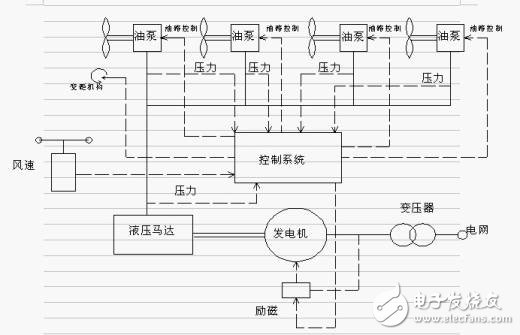
3.96mm (0.156") Pitch Wire to Board Connectors delivering 7.0A and 600V per circuit in an industry-standard 3.96mm pitch, power application connectors are ideal for low- to mid-power wire-to-board and board-to-board applications
3.96mm Pitch Board-to-Wire Connectors are rated for up to 10 Amps max. when using 16 AWG wire. The locking mechanism provides a clear and tactile click that prevents incomplete mating and incorrect insertion. The pin header comes with a guide post to prevent reverse insertion on the PCB. The lance is part of the housing instead of being a part of the terminal, which prevents tangled wires during assembly. The wall structure between the contacts helps to isolate the contacts and prevents short circuits between contacts. The DF63 series is capable of being potted, up to 5mm. Glass-reinforced resin is used on the pin header to prevent solder cracks due to thermal contraction. Keying options prevent incorrect connections due to the use of multiple connectors on the same board. When using identical pin counts, two versions are available with different keying options.
3.96mm Pitch Board-to-Wire Connectors Features
Capacity to handle a maximum of 10A when using 16 AWG wire MAX 10A/pin AWG ♯16 7A AWG ♯18
A locking mechanism that ensures a secure and completed connection: The locking mechanism delivers a clear and tactile click the prevents incomplete mating
Prevents incomplete insertion of the crimp contact
Prevents incorrect insertion between different poles
Reverse mounting prevention to PCB: The pin header is equipped with a guide post to prevent reverse insertion on the PCB
Molded lance design: The lance is actually part of the housing instead of being a part of the terminal. This prevents tangled wires during assembly
Short-circuit prevention: The wall structure between the contacts helps to isolate the contacts and prevents short circuits between contacts
Capable of being potted, up to 5mm
Solder Crack prevention: Glass-reinforced resin is used on the pin header to prevent solder cracks due to thermal contraction
Keying options prevent incorrect connections due to the use of multiple connectors on the same board. When using identical pin counts, two versions are available with different keying options
Corresponds with 7.92mm pitch: Also corresponds with 7.92mm pitch with 2 or 3 pos. without pins
Pitch 3.96mm Wire to Board Connectors Specification
Pitch:3.96mm
Circuits:2-12P
Wire AWG:18-24
Current:7.0 A
Rated Voltage: 250V
Operate TEMP: -25℃~85℃
Resistance:1000/min(MΩ)
Withstanding Voltage:1500V
Max wire(Diameter) : 2.5
Pitch 3.96mm Wire to Board Connectors Features and Benefits
Smallest pitch for positive lock Wire-to-Board crimp system
Provides space savings for mounting other components
mating retention with low mating and unmating forces
Wide header variations to provides customers with many choices and design flexibility
Easy to mate and unmate
Space saving SMT Mounting that provides assembly and cost efficiencies
Automated assembly reduces manual labor processes
Pitch 3.96mm Wire to Board Connectors Application industry:
Automotive
Electronic modules
Consumer
Air conditionerMobile POS terminalsNotebook PCSmart metersTVsTelevisions UAVs/Drones
Industrial
Servo motor
Medical
Patient Monitor
This is not a definitive list of applications for this product. It represents some of the more common uses.