Circuit Structure Analysis of High Frequency Switching Regulated Power Supply
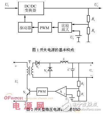
Switching power supplies have a series of advantages such as small size and high efficiency, and are widely used in various electronic products. However, due to the complicated control circuit of the switching power supply and the high output ripple voltage, the application of the switching power supply is also limited. The key to miniaturization and weight reduction of electronic devices is the miniaturization of the power supply, so it is necessary to reduce the loss in the power supply circuit as much as possible. The adjustment tube in the switching power supply operates in the switching state, and there is inevitably a switching loss, and the magnitude of the loss increases as the switching frequency increases. On the other hand, the loss of magnetic components and capacitors such as transformers and reactors in the switching power supply also increases with increasing frequency. At present, the power tube in the switching power supply on the market mostly uses bipolar transistors, and the switching frequency can reach several tens of kHz; the switching frequency of the switching power supply using MOSFET can reach several hundred kHz. In order to improve the switching frequency, high-speed switching devices must be used. For power supplies with a switching frequency above megahertz, a resonant circuit can be utilized. This mode of operation is called a resonant switching mode. It can greatly improve the switching speed. In principle, the switching loss is zero and the noise is small. This is a way to increase the operating frequency of the switching power supply. A megahertz converter using a resonant switching method has been put to practical use. The integration and miniaturization of switching power supplies has become a reality. However, integrating the power switch tube and the control circuit on the same chip must solve the problems of electrical isolation and thermal insulation. The basic configuration of the switching power supply The switching power supply uses a power semiconductor device as a switching device to adjust the output voltage by periodically interrupting the duty cycle of the switching device. The basic structure of the switching power supply is shown in Figure 1. The DC/DC converter performs power conversion. It is the core part of the switching power supply. In addition, there are circuits for starting, overcurrent and overvoltage protection, and noise filtering. The output sampling circuit (R1, R2) detects the change of the output voltage, and compares with the reference voltage Ur, the error voltage is amplified and pulse width modulated (PWM) circuit, and then the driving circuit controls the duty ratio of the power device, thereby adjusting the output voltage. the goal of. Figure 2 is a circuit implementation. The DC/DC converter has various circuit forms, and a commonly used PWM converter with a working waveform of a square wave and a resonant converter with a working waveform of a quasi-sinusoidal wave are commonly used. For a series linear regulated supply, the transient response of the output to the input is primarily determined by the frequency characteristics of the regulator. However, for a switched regulator, the transient change in the input is more at the output. While increasing the switching frequency, the transient response of the switching power supply can also be improved due to the improved frequency characteristics of the feedback amplifier. The load change transient response is mainly determined by the output LC filter characteristics, so the transient response characteristics can be improved by increasing the switching frequency and reducing the output filter LC product. Switching type regulated power supply classification Switching type regulated power supply has a variety of circuit structures: (1) divided by driving mode, self-excited and separately excited. (2) According to the working mode of DC/DC converter: 1 single-ended positive excitation and reverse excitation, push-pull, half-bridge, full-bridge, etc.; 2 step-down, step-up and step-down type. (3) According to the circuit composition, there are resonant and non-resonant types. (4) According to the control method: 1 pulse width modulation (PWM); 2 pulse frequency modulation (PFM); 3PWM and PFM hybrid. (5) According to the power supply isolation and feedback control signal coupling, there are isolated, non-isolated and transformer-coupled, optocoupler and so on. The combination of the above methods can constitute a plurality of types of switching regulator power supplies. Therefore, the designer needs to effectively combine the characteristics of various modes to produce a high-quality switch-type regulated power supply that meets the needs. Compact Temperature Sensor We have many products in marine temperature sensors, and our small marine temperature sensors have been traveling in various oceans. Our sensors are not only used in ship mechanical equipment, but also used in freight yards. Our small marine temperature sensor can be used to monitor the marine mechanical equipment and the temperature and humidity in the warehouse. Moreover, our sensor has been used in the oil separator module for a long time, and its performance is very stable. Compact Temperature Sensor,Small Temperature And Humidity Sensor,Smart Temperature Sensor,Hydraulic Temperature Sensor Taizhou Jiabo Instrument Technology Co., Ltd. , https://www.taizhoujiabo.com