Detailed memory mapping of STM32
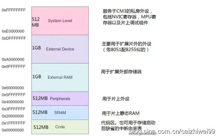
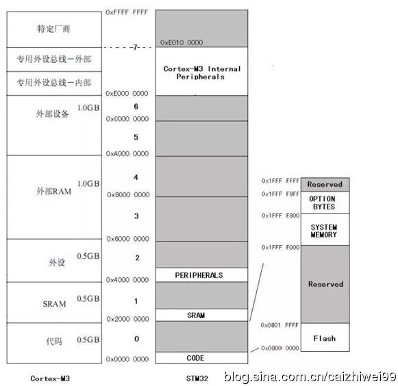
Memory mapping refers to the unified addressing of FLASH, RAM, peripherals, BOOT, BLOCK, etc. in or outside the chip. That is, the address is used to represent the object. The vast majority of this address is stipulated by the manufacturer, and the user can only use it and cannot change it. Users can only customize when external RAM or FLASH is attached. The Cortex-M3 supports 4GB of storage space, and its storage system uses a unified addressing method; program memory, data memory, and registers are organized in a 4GB linear address space and stored in a little-endian format. Since the Cortex-M3 is a 32-bit kernel, its PC pointer can point to the address space of 2^32=4G, which is 0x0000_0000 - 0xFFFF_FFFF. see picture 1: Figure 1: Cortex-M3 memory map The Cortex-M3 core divides the 4x size of 0x0000_0000 - 0xFFFF_FFFF into 8 blocks: code, SRAM, peripherals, external RAM, external devices, dedicated peripheral bus - internal, dedicated peripheral bus - external, vendor-specific ( see picture 1). This has led to the need for chip manufacturers using the core to design memory structures for their respective chips, such as stm32. Figure 2: Cortex-M3 vs. medium density stm32 memory map comparison As you can clearly see in Figure 2, the memory structure of STM32 is very similar to that of Cortex-M3 (this is because stm32 originally designed hardware according to the cortex_m3 kernel). The difference is that STM32 adds a lot of practical things, such as : Flash, SRAM, etc. Only by adding these things can you become a practical and working processing chip - STM32. The memory address space of STM32 is divided into 8 equal-sized areas, each of which is 512MB in size (eg, 0x20000000~0x40000000). Mastering the knowledge of STM32 memory is actually mastering the knowledge of the two areas of Flash and SRAM. The SRAM size of different types of STM32 microcontrollers is different, but their starting addresses are 0x2000 0000, and the termination addresses are 0x2000 0000+ their fixed capacity. The understanding of SRAM is relatively simple. Its function is to access various dynamic input and output data, intermediate calculation results, and data exchanged with external memory and temporary data. After the device is powered off, the data stored in the SRAM is lost. STM32 Flash, strictly speaking, should be a Flash module. The names of the three partitions are consistent with the datasheet. The Flash module includes: Flash main memory (Main memory) Flash: where the code is stored, as shown in Figure 2, the FLASH area: 128KB (0x08000000~0x0801ffff) (Flash termination addresses of different capacities are different); Flash information area (Information block), which can be divided into Option Bytes and System Memory areas; System Memory: STM32 has been solidified for a while in the system memory (medium-density devices address: 0x1FFF_F000, size 2KB) memory. This program is a fixed and unchangeable Boot Loader (see the description of the programming manual PM0042). Option Bytes: It can be configured according to the user's needs (such as configuring the watchdog as hardware implementation or software implementation); the model address is the same except for the interconnect type: (0x1fff_f000~0x1fff_f80f) The termination address in the figure is incorrect: it should be 0x1fff_f80f , exactly 16 bytes. Flash memory interface (Flash memory interface) for on-chip peripherals. Is the PERIPHERALS region starting from 0x40000000 in Figure 2. Also known as a peripheral memory map, the operation of this area is to operate on the corresponding peripheral. According to the memory map of the STM32, in the code area, the address 0x00000000 is the boot area. After power-on, the CPU starts executing code from this address. 0x08000000 is the starting address of the user FLASH, and 0x20000000 is the starting address of the SRAM. Air conditioning heating: After turning on the heating function, the high-temperature coolant in the engine will flow through the heating water tank. At this time, the air blown by the blower will also pass through the heating water tank, so that the air outlet of the air conditioner can blow warm air. Refrigeration of car air conditioner: After pressing the ac button, the compressor clutch of the car air conditioner will be engaged. At this time, the engine will drive the compressor to operate. The compressor can continuously compress the refrigerant and deliver the refrigerant to the evaporating box. The refrigerant is evaporating The inside of the box will expand and absorb heat so that the refrigerant can cool the evaporating box. Cross-Flow Fan,Cross Flow Blower,Cross Flow Blower Fan,Cross Flow Cooling Fan Original Electronics Technology (Suzhou) Co., Ltd. , https://www.original-te.com