Using a specific example to analyze several different methods of performing current detection on a voltage rail
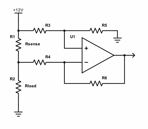
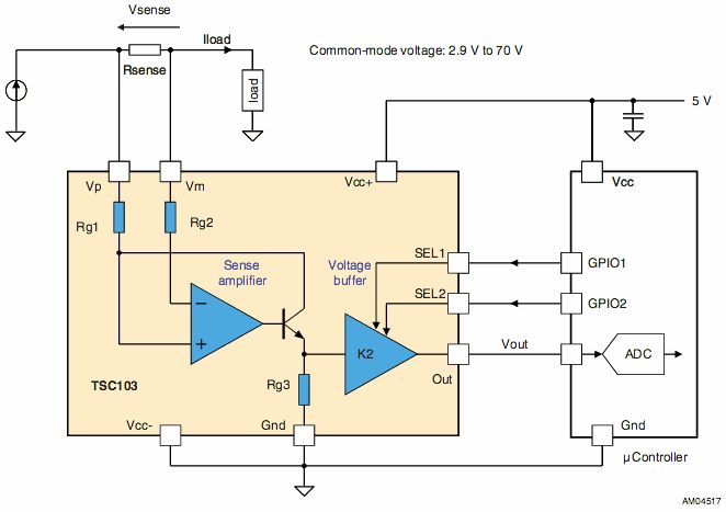
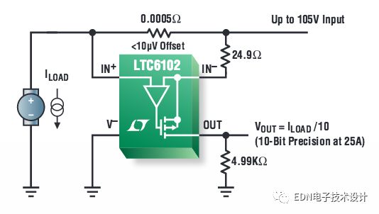
This article uses a specific example to compare several different methods of performing current sensing on a voltage rail. The first method is to use a single op amp differential amplifier with discrete resistors; the second method is to use V+ instead of ground as the reference rail; the third method is common in IC solutions where transistors are used. Works with an op amp to measure with a ground reference current. As an editor of the EDN "Design Example" column, I will face a lot of design submissions, both good and not too good. The high-end current detection circuit mentioned in an article recently abandoned for various reasons has many problems. This reminds me of different ways of implementing current sensing on a voltage rail. The core design idea of ​​most DC current detection circuits is to start with the resistors in the power supply line (although magnetic field induction is a good choice, especially in the case of high current). One simply measures the voltage drop across the resistor and adjusts the resistance as needed to read the current (E = I × R, if you don't include this, someone will complain). If the sense resistor is on the ground branch, then the solution is a simple op amp circuit. Everything is based on the ground, just pay special attention to the small voltage drop in the grounding layout. However, the preferred method is usually to place the sense resistor in the power line. why? Because grounding may not be feasible (for example, grounding automotive electronics through the chassis), or you may not want the equipment ground to be different from the power ground (which can cause ground loops and other problems). So what should I do? The most obvious way is to bridge a differential or instrumentation amplifier (inamp) across the sense resistor, but this is actually not a good idea. In order to accurately detect current, an extremely high CMR (common mode rejection) is usually required, which is expensive and easy to drift. Why do you say that? Let's look at a design example: 0-10A, 12V nominal, 5mΩ sense resistor. Figure 1: The most obvious high-side current sensing scheme uses a differential amplifier. This solution does not even need to consider the use of discrete resistors unless they are part of a precision-matched network (and therefore, of course, not truly separate). For a 1V supply voltage offset and a 80dB differential amplifier CMRR (which means about 0.01% of the resistor match), you will see a current drift equivalent to 20mA (1V variation, 80dB CMRR resulting in an input 0.1mV offset, then Divided by the 5mV/A calibration of the 5mΩ sense resistor). For a 0-12V supply, multiply the offset current by 240mA over a voltage range of 12:V. Note that a true three op amp instrumentation amplifier is less sensitive to resistor matching than a single op amp differential amplifier. However, there is usually a better way. The "design example" mentioned above uses a single op amp differential amplifier with discrete resistors. In fact, a resistor can be adjusted with a potentiometer, which I originally thought was used for CMRR, but the result was gain adjustment! If the supply voltage is stable, in a sense, this method works – but it is not a good idea. The second high-end detection method requires a little lateral thinking. I changed my mind and used V+ instead of the ground as a reference track. This is conceptually like the low-end detection of a negative voltage source, which is a good solution if you can level it. Figure 2: The output is further processed (for example, a comparator) with V+ as a reference. R4 is optional for protection. The third method, which is now common in IC solutions, uses transistors and op amps together to provide a ground reference for current measurements. When I thought of an inverted op amp, I didn't know the design, which might be a good thing because I saved a transistor. Figure 3: ST's TSC103 uses a BJT in the loop. Figure 4: Linear's LTC6102 uses a MOSFET. STMicroelectronics, Maxim, and Linear offer such devices, but you can easily implement such circuits yourself. Conductor Inspection Bicycles or Car of various types including Spacer Bike, Spacer Car, 1 bnd Spacer car, 2 bnd Spacer car, Four Bunle Spacer car, Spacing Bike, Spacing Car, Spacer, which is widely used to used to install or repair accessories on splited conductors. It can be going through on splited conductors so it is very convenient for working and repairing accessories while stringing electric power lines. It is made of high quality and high strength steel material with reasonable volume, light weight, easy to operate. By high quality material and good design, these kind of Spacer Bike or Car can be durable and long service life. we are a professional Chinese exporter of Spacer Bike or Car and we are looking forward to your cooperation. Overhead line bicycles, conductor inspection bicycles, lineman spacer buggy, spacer carts, spacer buggy Yangzhou Qianyuan Electric Equipment Manufacturing & Trade Co.Ltd , https://www.qypowerline.com