MSP430 microcontroller selection and series introduction
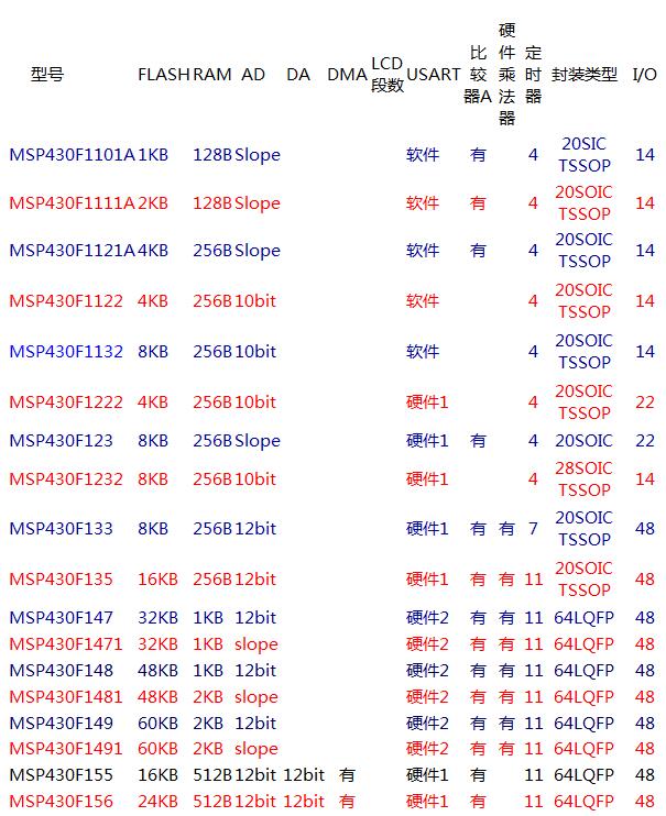
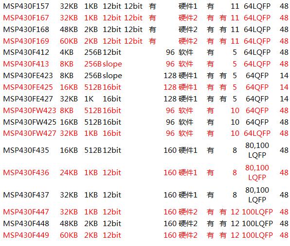
In the selection of MSP430, we mainly focus on the FLASH type MCU which is now more popular. Because the current mainstream MCU is also based on FLASH type, it is widely used. Therefore, we have also made a selection list for the FLASH type of MSP430. If you want to know other models that are not listed, please contact TI. MSP430 FLASH type MCU selection table: MSP430 microcontroller family detailed: MSP430x1xx series Ultra-low-power MCUs based on flash or ROM, offering 8MIPS, operating from 1.8V to 3.6V, with up to 60KB of flash memory and a variety of high-performance analog and intelligent digital peripherals. Ultra low power consumption as low as: 0.1μA RAM Hold Mode 0.7μA Real Time Clock Mode 200μA/MIPS Operating Mode Quickly wakes up from standby mode within 6μs Device parameters: Flash options: 1KB – 60KB ROM Options: 1KB – 16KB RAM Options: 512B – 10KB GPIO Options: 14, 22, 48-pin ADC Options: 10 and 12-bit slope SAR Other integrated peripherals: analog comparator, DMA, hardware multiplication , SVS, 12-bit DAC [5] MSP430F2xx series Flash-based ultra-low-power MCUs with up to 16MIPS over the 1.8V to 3.6V operating voltage range. Includes very low power oscillator (VLO), internal pullup/pulldown resistors, and low pin count selection. Ultra low power consumption as low as: 0.1μA RAM Hold Mode 0.3μA Standby Mode (VLO) 0.7μA Real-Time Clock Mode 220μA/MIPS Operating Mode Ultra-quickly wakes up from standby mode within 1μs Device parameters: Flash Options: 1KB – 120KB RAM Options: 128B – 8KB GPIO Options: 10, 16, 24, 32, 48, 64 Pin ADC Options: 10 and 12 Bit Slope SAR, 16 Bit Sigma-Delta ADC Other Integrated Peripherals: Analog Comparator, Hardware Multiplier, DMA, SVS, 12-Bit DAC, Operational Amplifier [6] MSP430C3xx series The older ROM or OTP device family operates from 2.5V to 5.5V with up to 32KB ROM, 4MIPS and FLL. Ultra low power consumption as low as: 0.1μA RAM Hold Mode 0.9μA Real Time Clock Mode 160μA/MIPS Operating Mode Quickly wakes up from standby mode within 6μs Device parameters: ROM option: 2KB – 32KB RAM Option: 512B – 1KB GPIO Options: 14, 40-pin ADC Option: 14-bit slope SAR Other integrated peripherals: LCD controller, hardware multiplier MSP430x4xx series A family of LCD flash or ROM based devices offering 8-16MIPS, including an integrated LCD controller, operating from 1.8V to 3.6V with FLL and SVS. Ideal for low power measurement and medical applications. Ultra low power consumption as low as: 0.1μA RAM Hold Mode 0.7μA Real Time Clock Mode 200μA/MIPS Operating Mode Quickly wakes up from standby mode within 6μs Device parameters: Flash/ROM option: 4kB – 120KB RAM Options: 256B – 8KB GPIO Options: 14, 32, 48, 56, 68, 72, 80 Pin ADC Options: 10 and 12-bit slope SAR, 16-bit Σ-Δ ADC Other integration Peripherals: LCD controller, analog comparator, 12-bit DAC, DMA, hardware multiplier, operational amplifier, USCI module [8] MSP430F5xx series The new flash-based product family features the lowest operating power consumption and performance up to 25MIPS over the 1.8V-3.6V operating voltage range. Includes an innovative power management module to optimize power consumption. Ultra low power consumption as low as: 0.1μA RAM Hold Mode 2.5μA Real Time Clock Mode 165μA/MIPS Operating Mode Quickly wakes up from standby mode within 5μs Device parameters: Flash Options: Up to 256KB RAM Option: Up to 16KB ADC Options: 10 and 12-bit SAR Other Integrated Peripherals: USB, Analog Comparator, DMA, Hardware Multiplier, RTC, USCI, 12-Bit DAC [9] MSP430G2553 Low supply voltage range: 1.8v to 3.6v. Ultra-low power operation mode: 230μA (at 1MHz frequency and 2.2V) Standby mode: 0.5μA Off mode (RAM hold): 0.1μA 5 energy saving modes On-chip comparator for analog signal comparison or slope analog-to-digital (A/D) conversion Quickly wake up from standby mode in less than 1μs 16-bit reduced instruction set (RISC) architecture with 62.5 ns instruction cycle time 10-bit 200-ksps analog-to-digital (A/D) converter with internal reference, sample and hold, and auto-scan Basic clock module configuration – Internal frequency serial board programming with four calibration frequencies up to 16MHz, – The internal ultra low power low frequency (LF) oscillator requires no external programming voltage. – 32kHz crystal protection – External digital clock source with on-chip emulation logic with two-wire (Spy-Bi-Wire) interface Two 16-bit TImer_A with three capture/compare registers Up to 24 I/O pins that support touch sensing
24v wall charger,24v dc adapter,24v ac dc adapter,24v switching adapter,100-240V AC to DC 24V 3A 72W Power Adapter,12W Ac Switching Power Adapter,24V 0.5A Power Supply For Led Lights Shenzhen Waweis Technology Co., Ltd. , https://www.waweis.com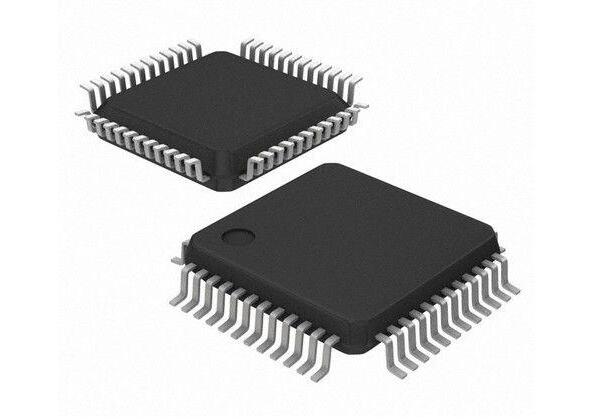
24V Switching Wall Charger

About this item