Spectrophotometer verification procedures in detail
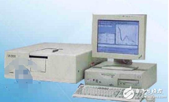
The V-2450 is an ultra-visible UV-Vis spectrophotometer that offers high performance and easy operation. It is combined with the powerful operating software UVProbe to provide powerful functions. The optical system of the small spot makes the measurement of trace amounts more convenient. 1. High level of ultra low stray light UV-2550 uses ultra-low DDM (double blazed diffraction grating, dual monochromator) technology to achieve ultra-low stray light (below 0.0003%) and high luminous flux. Although the UV-2450 uses a single monochromator, the stray light is also below 0.015%. Low stray light can be directly measured without diluting a high concentration sample. 2. Universal software UVProbe UV-2450/2550 is controlled by UVProbe, a new generation of Chinese and English bilingual operating software. It includes four modules: spectrometry, photometry, kinetics measurement and report processing. It can be realized from basic measurement to research analysis. UVProbe implements true QA/QC functionality and fully supports GLP and GMP. In addition, software such as film thickness measurement and color analysis can be loaded. 3. Rich accessory selection and wide application areas Life sciences: Tests on trace samples obtained from life. Integrating sphere test: turbid and powdery samples can be tested. Reflective attachment: The determination of relative and absolute reflection of optical materials. The working band of the instrument is 190~900nm, and it is divided into two sections of 190~340nm and 340nm~900nm respectively. 1.1 Maximum allowable error of wavelength: A segment: ±0.5, B segment: ±1.0 1.2 Wavelength repeatability: Section A: ≤ 0.2, Section B: ≤ 0.5 1.3 Noise and drift: 0% transmittance: ≤ 0.1; 100% transmittance: ≤ 0.2; drift: ≤ 0.2 1.4 Transmittance maximum allowable error: A segment: ±0.5, B segment: ±0.5 1.5 Transparency repeatability: Section A: ≤ 0.2, Section B: ≤ 0.2 1.6 stray light: A segment: 220nm, ≤ 0.2; B segment: 360nm, ≤ 0.2, 420nm, ≤ 0.5 1.7 absorption pool matching: quartz: 220nm, 0.5; glass: 440nm, 0.5 2.1 Mark: name, model number, manufacturer name, date of manufacture, working power supply voltage, frequency. 2.2 Appearance: 2.2.1 All fasteners of the instrument should be fastened, and each adjustment knob, button and switch can work normally. Cable plugs are tight fit and well grounded. 2.2.2 The instrument should be placed on the workbench smoothly and the sample holder positioned correctly. 2.2.3 The indicator engraved line is even and clean, the digital display is clear and complete, and the adjustable parts should not have stuck, sudden jump and significant empty return. 2.3 Absorption pool: The absorption tank shall not have cracks, and the light-transmitting surface shall be clean and free of scratches and spots. 3.1 wavelength reference material 3.1.1 mercury lamp 3.1.2 Titanium oxide, lanthanum and cerium filters with wavelength standard values ​​at three spectral bandwidths of 1, 2, and 5 nm 3.1.3 titanium oxide solution, 40 g/L 3.1.4 Interference filter: wavelength peak standard uncertainty ≤ 1nm, spectral bandwidth "15nm3.2 transmittance standard material 3.2.1 0.001 mol/L perchloric acid standard solution of potassium dichromate with a mass fraction of 0.06000/1000 3.2.2 ultraviolet transmittance filter 3.2.3 Spectral neutral filter with a nominal transmittance of 10%, 20%, 30% 3.3 stray light reference material 3.3.1 Cut-off filter, the wavelengths are 220, 360, 420nm, the half-height wavelengths are 260, 400, 470nm, the cut-off wavelength is not less than 225, 365, 430nm, the cut-off area absorbance is not less than 3, the light-transmitting area The average transmittance is not less than 80%. 3.3.2 sodium iodide standard solution, the concentration is 10.0g / L 3.2.3 sodium nitrite standard solution, the concentration is 50.0g / L 3.4 standard quartz absorption cell: the specification is 10.0mm, and the transmittance error is not more than 0.2%. 4.1 Temperature: 10-35 ° C 4.2 Relative humidity: no more than 85% 4.3 Power supply: voltage 220±22V, frequency 50±1Hz 4.4 The instrument should not be exposed to strong light, no strong magnetic field or electric field interference, no strong air current and corrosive gas. 5.1 General technical requirements 5.2 Wavelength difference error and repeatability 5.3 Noise and drift 5.4 transmittance error and repeatability 5.5 stray light 5.6 absorption pool matching 6.1 General technical requirements inspection: visual inspection, manual inspection 6.2 Wavelength maximum allowable error and wavelength repeatability 6.2.1 Reference materials 6.2.2 Verification steps Set the wavelength scan range of the instrument according to the selected calibration wavelength (if the wavelength scan range is wide to allow segmented scanning), the common spectral bandwidth, slow scan, and the sampling interval smaller than the instrument wavelength repeatability index. Use transmittance or absorbance measurement method, use the air as blank to adjust the baseline of the instrument according to the set scanning parameters, use the light barrier to perform dark current correction, then set the standard material perpendicular to the sample light path, set the appropriate recording range, and continuously scan. Three times, the transmittance ratio valley or the absorption peak wavelength λi was detected. Calculation of results: Calculate the wavelength indication error for each measurement wavelength according to the following formula: ∆λ=ï λ-λn Where: ï λ - the average of 3 measurements Λn——wavelength standard value Calculate wavelength repeatability as follows: ï¤Î»=λmax-λmin Where: λmax, λmin are the maximum and minimum values ​​of 3 measurement wavelengths respectively 6.2.3 Noise and drift 250nm, 500nm is selected as the noise measurement wavelength; 500nm is the drift measurement wavelength. Set the instrument scanning parameters as: time scanning mode (or fixed wavelength scanning), the spectral bandwidth is 2nm (the instrument with constant spectral bandwidth is unchanged), the sampling time interval is 1s, the photometric measurement method is transmittance, and the recording range is 99%~101% ( The non-scanning instrument is not set. The reference beam and the sample beam are treated as air blanks at each measurement wavelength. The transmittance of the instrument is adjusted to 100%, and the difference between the maximum value and the minimum value is measured on the measurement spectrum for 2 minutes (non-scanning instrument records) The maximum and minimum values ​​within 2 min) are 0% noise of the instrument transmittance. When the wavelength is switched, the light is allowed to stabilize for 5 min. Automatic scanning instrument, after testing the transmittance 0% and 100% noise according to the above requirements, the wavelength is placed at 500nm, scanning for 30min, and the difference between the maximum and minimum values ​​of the center line of the scanning envelope is the transmittance of the instrument. 100 line drift. 6.2.4 Transmittance maximum allowable error and repeatability 6.2.4.1 The transmittance is measured three times at 235, 257, 313, 350 nm using standard materials and standard absorption cells. 6.2.4.2 The transmittance of the spectral center filter with a nominal transmittance of 10%, 20%, and 30%, at 440 nm, 546 nm, and 635 nm, with air as a reference, measures the transmittance. 6.2.4.3 Calculation of results Calculate the transmittance error as follows ∆T=ï T-Tn Where: ï T——average of 3 measurements Tn - transmittance standard value Calculate transmittance repeatability as follows ï¤T=Tmax-Tmin Where: Tmax, Tmin - the maximum and minimum values ​​of the measured transmittance in 3 times 6.2.5 stray light The standard substance is selected and the transmittance of the standard substance is measured at the corresponding wavelength, and the transmittance value is the stray light of the instrument at the wavelength. Part A is measured with a sodium iodide standard solution (or cut-off filter) at 220 nm, a nitrite standard solution (or cut-off filter) at 360 nm (tungsten lamp), a 10 nm standard quartz absorption cell, and distilled water as a reference. Transmittance value. The B-stage prism type instrument uses a cut-off filter at a wavelength of 420 nm with air as a reference to measure the transmittance. 6.2.6 absorption pool matching The same optical path absorption tank attached to the instrument is filled with distilled water at 220 nm (quartz absorption cell) and 440 nm (glass absorption cell), and the transmittance of one absorption cell is adjusted to 100%, and the transmittance values ​​of the other cells are measured. The difference is the matching of the absorption pool. For instruments with a transmission ratio of only 0-100%, 95% can be used instead of 100%. 6.3 Processing of verification results The lowest level of the verification result indicates the instrument qualification level; if one of the inspection items fails to meet the requirements, it is judged as unqualified, and the verification result notice is issued, indicating the unqualified items. 6.4 verification cycle The verification period is generally not more than 1 year. During this period, when the instrument is repaired or there is doubt about the result, it should be verified in time. High voltage
Resistor dividers (RFD Series)
are suited for all the fields of high voltage and small signal multiply. Such as
Such as High voltage power
supply, Medical electronical devices,
Audiophile speakers, Audio systems, Smoke sensors, Infrared detectors, Radiation detectors, Special gas detectors
High Voltage Polyester Capacitor,High Voltage Divider,Flat High Voltage Divider,High Voltage Resistor Dividers,High Power Resistor XIAN STATE IMPORT & EXPORT CORP. , https://www.shvcomponents.com