Summary of 5 common problems in 51 single chip application
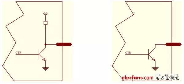
This article summarizes some common problems in the application of 51 single-chip microcomputers. This is what I actually encountered. Because of the limitation of the length of the article, these problems are far from enough to express the common problems of the single-chip microcomputer. I hope to help beginners. Please give pointers to the imperfections in the text. Thank you! It is implemented by predefined, for example: sfr P0 = 0x80; sbit P0_0 = 0x80; the former declares that the P0 port address is at 0x80, and the latter indicates the bit 0 of the P0 port, that is, P0.0 is located in the bit address space 0x80. These two 0x80s have completely different meanings and are distinguished by the keywords sfr and sbit. Thus when the program is compiled, the compiler will compile into the corresponding assembly language accordingly. E.g: C51 statement: P0 = 1; P0 is declared as sfr, so it is compiled into: mov 80h, 01h, which will send 0x01 data to 0x80 unit. Since 0x80 unit physically corresponds to P0 port, P0.0 pin will output high level (in fact, it shows high resistance state). , P0 port unique), other .1-.7 pin output low level. C51 statement: P0_0 = 1; P0_0 is declared as sbit, so it is compiled into: setb 80h, which sets the value of the bit of the 0x80 address of the bit address space. This bit is the bit 0 of the P0 port. After execution, P0.0 will output a high-impedance state. And P0.1-.7 will not change. A significant advantage of the 51 MCU is that the instruction execution time is fixed, so it can be adapted to occasions with strict timing requirements. For example, the cpu card that conforms to the ISO7816 protocol is read and written, and the timing requirements are strict. In fact, it is a synchronous half-duplex serial port made with io feet. Programs that support cpu cards are generally large and need to be organized with c51, but due to the uncertainty of c compilation, the underlying program must be packaged into assembly language modules embedded in the project. This brings up a few questions: how to declare functions, how parameters are passed, and so on. Due to space limitations, it cannot be said very fine. The following examples: The assembler saves a separate file and adds it to the project. The function is as follows: _proc_a: Mov a, r7 Inc a Mov r7, a Ret Declare in the .h file with the c language: extern unsigned char proc_a(unsigned char val); The call is like: retvalue = proc_a(0x11); Description: a: If the assembler takes parameters, you need to add an underscore before the assembler. The place to declare it does not need to be added (the Weifu compiler requires it). b: The first parameter in the formal parameter of the function is passed with R7, and the return value of the function is returned with R7, which is the general specification of C51. Other parameters are specified accordingly. The function can return a bit, which is returned with the c bit of psw. c: The above statement, the execution order is to give 0x11 to R7, then jump to the subroutine, and the subroutine adds it to 1 and sends it back. d: When the function jumps to the assembler, the R0-R7, A, B, PSW, DPTR and other registers in this area can be used by the subroutine. It is not necessary to consider whether to restore these regular resources after the call. In the above example, the value of A is used by the function, and the programmer does not have to restore the value before the call. Many newcomers have encountered this problem, in fact it is very simple, which involves how the io foot of the chip is made. This is very important for hardware engineers. TTL io foot model: P1, P2, P3 can be understood as the left picture. Note that there is a resistor under vcc, so it can be understood as: the ability of pin output 1 is weak. There is no resistor on the ground side, which can be understood as a strong ability to sink current into the pin. The P0 port can be understood as the right picture. This is the open collector output, also known as the OC output. It can be seen that when CTR=1, the triode is turned on and the pin is grounded; when ctr=0, the triode is turned off, and the pin is floating, also called tristate. The purpose of this port is to consider P0 shoulder negative read and write data and address multiplexing, this relationship should carefully understand the cpu timing diagram. Therefore, the P0 port should be added with a suitable pull-up resistor, and never add a pull-down resistor. The choice of pull-up resistor depends on the external load. As can be seen from the left figure in the previous section. When the output is made, ctr=1 outputs a strong signal 0, and ctr=0 outputs a weak signal 1. When the io pin is input, ctr=0 should be made so that the triode is turned off. If the external signal is 1, the pull-up resistor strengthens this 1, and the microcontroller reads 1. When the external signal is 0, be careful that the pull-up of the pull-up resistor must be fully cancelled to get 0 on the pin. Therefore, for the program, setting the io pin to 1 is in the receiving state, and of course the output 1 state. The program sets the io port to 1. If the read signal is not 1, it depends on the external circuit. If the external circuit does not “eat†the current of the pull-up resistor, the read will get 1, otherwise, although the program sets the io pin to 1, But the reading is 0. Therefore, if the external circuit is driven with the high level of the io pin, be careful that the external circuit "eats" this 1 and cannot output 1. As an input, a peripheral that is 0 level must be strong enough to pull the io pin low. Therefore, when using io feet to directly light the led, it is best to use the inverse logic, that is, output 0, let the led light. This ensures the drive capability. That is, the io pin is connected to the negative end of the led, and the positive terminal of the led is connected to the vcc. Therefore, when the io pin outputs 1, it is irrelevant for the external circuit to forcibly ground it. When the io pin outputs 0, the external circuit forcibly connects the power supply and the io pin is damaged. Therefore, after the program is powered up, all io ports are generally written as 1: MOV P0, 0FFH. The P3 port pins are multiplexed, and all pins must be in the output 1 state. For example, if the RXD pin is output as 0, then it can't read any data. The author has debugged it for a whole day and found that the serial port does not receive data. It is not the reason for setting RXD, and the time is wasted on the periphery. Very shameful. The crystal oscillator of the microcontroller can be simplified internally into an inverter. When the crystal input pin XI just passes the swell and is considered to be 1, the output pin XO outputs 0. This 0 will drive the crystal to lower the XI voltage. When it is lowered to the moment when the swell is considered to be 0, the output pin XO outputs 1. This is the beginning of the week. Therefore, when observing the normally working crystal input pin XI with an oscilloscope, an approximate horizontal line is obtained which is not high or low. XO is a sine wave with a large amplitude. When measuring the crystal input pin XI, the oscilloscope test pen should be placed on the X10 file. Otherwise, the test pen can stop the crystal. Therefore, when wiring, the crystal input pin XI should be as close as possible to the crystal, and the XO pin can be slightly farther. At the same time, XO has a certain driving capability, and some chips can use it to drive other sequential circuits (not recommended because system reliability is degraded). Written here, I found that the problem of 51 single-chip is too much, this text is simply a drop in the ocean. Desktop Phone Holder,Desktop Mobile Phone Holder,Adjustable Desktop Phone Holder,Universal Desktop Cell Phone Holder Ningbo Luke Automotive Supplies Ltd. , https://www.nbluke.com