Using a single-chip system to develop a two-wheeled balance car case sharing
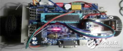
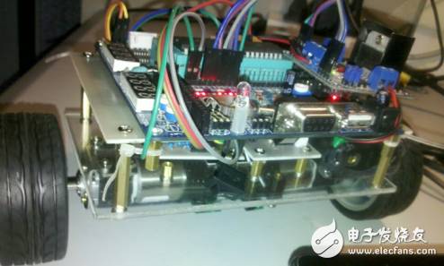
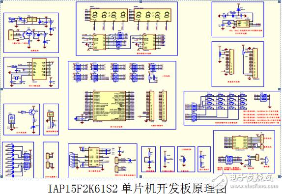
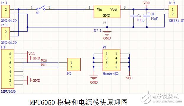
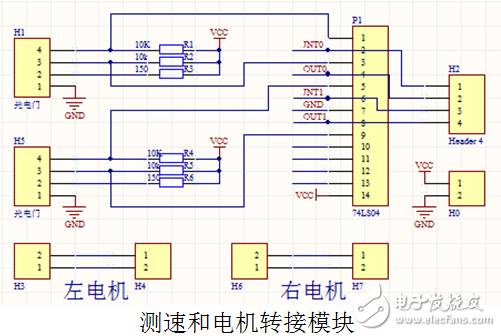
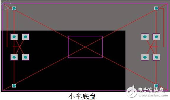
In foreign countries, two-wheeled manned balance vehicles have long been used in some public places. Today, many airports, railway stations, bus stations and other public places use two-wheeled manned balance vehicles. Studying the two-wheeled balance car is conducive to the study of two-wheeled manned balance car. This work is mainly composed of an IAP15F2K61S2 MCU development board as the main control board, a power supply and sensor module to collect the angle data and supply power to the system, a speed measurement module to measure the speed information of the motor, and finally convert the angle information into a PWM output to a motor. The drive module controls the two hollow cup motors. This design is based on the IAP15F2K61S2 single-chip system developed two-wheel balance car, using IAP15F2K61S2 microcontroller development board as the main control board, using MPU6050 gyroscope and acceleration sensor to collect acceleration and angular velocity, calculate the angle to determine the attitude of the car, and then through the photoelectric door The sensor measures the motor speed of the car to calculate the vehicle speed. The PID algorithm is used to perform PWM output on the motor drive according to the data measured by the sensor, and the appropriate PID parameters are adjusted to make the car stand upright. This work is easy to use and can be erected by turning on the main switch. The two-wheeled manned balance car has certain advantages in some public places. Studying the two-wheeled balance car has certain help for the development of two-wheeled manned balance car. This work has the characteristics of simple and clear structure and convenient use. design feature: The car chassis is that we use the vernier caliper to measure the aperture and position of the motor bracket, draw the chassis model with Altium Designer software, and then engrave the chassis with engraving machine and acrylic plate. The installation of the sensor module and the battery compartment on the car is symmetrical, so that the center of gravity of the car is above the motor. The sensor installation is slightly higher than the motor, probably at the center of gravity, which helps the balance and stability of the car. In the algorithm, we use the reduced PID algorithm and the Kalman filter algorithm to control the motor, making the system more stable and reliable. Platform selection instructions: This system adopts IAP15F2K61S2 MCU development board as the main control board, IAP15F2K60S2 is 1T 8051 MCU. It is a true single-chip microcomputer with wide operating voltage, no external reset circuit and external crystal oscillator, and internal crystal oscillator 5-33.1776M is optional. Rich on-chip peripherals, with 3-channel capture/comparison unit (CCP/PCA/PWM), 8-channel 10-bit high-speed AD, three timer/counters, dual serial port, high-speed serial communication ISP interface, large-capacity on-chip EEPROM. The motor drive adopts LM298N, the speed measurement adopts transmissive photoelectric gate, the signal outputs stable pulse through the inverter, and the motor adopts hollow cup, the frequency can reach more than ten kilohertz. The internal resources of the IAP15F2K61S2 microcontroller used in this work include timer 1, timer 2, serial port 1, ADC, external interrupt 0, external interrupt 1, PWM and other resources. Timer 1 processes data in a 10ms cycle, Timer 2 acts as a baud rate generator for serial port 1, serial port 1 is used to communicate with the host computer software during debugging, and ADC is the voltage at the adjustable end of the collector potentiometer for debugging PID parameters. External interrupt 0, 1 is used to count the pulse of the speed measuring module, and PWM is used as the enable motor to drive the input signal. MPU6050 uses IIC communication to transmit data, and the power module uses LM7805 ($0.2053) as the voltage regulator chip to supply power to the microcontroller and sensor. There are two photoelectric gates at the end of each motor for speed measurement, and the photoelectric gate output signal is more stable and reliable after being output by the inverter. Adapter plate transfer for motor wiring helps protect motor wiring. k eep out layer border, top-level drawing auxiliary line, use the engraving machine to punch first and then cut the edge. Design Notes: Based on the IAP15F2K61S2 microcontroller development board, the design uses the gyroscope and the acceleration sensor to measure the angle information with a period of 10ms. After the Kalman filter algorithm filters and processes the output through the PD algorithm, the speed measurement module measures the speed with a period of 100ms. The information is filtered by the complementary filtering algorithm and then processed by the PI algorithm, and the output of the angle loop and the output of the speed loop are combined as the set value of the PWM to the motor drive input to control the motor. Fully Transparent Liquid Crystal Display Fully Transparent Liquid Crystal Display,Industrial Instrument Lcd Display,Household Appliances Lcd Display,Fire Facility Instrument Display Dongguan Yijia Optoelectronics Co., Ltd. , https://www.everbestlcdlcm.com