Voltage type inverter DC link filter capacitor calculation method - Database & Sql Blog Articles
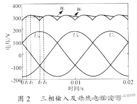
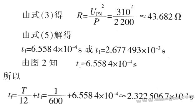
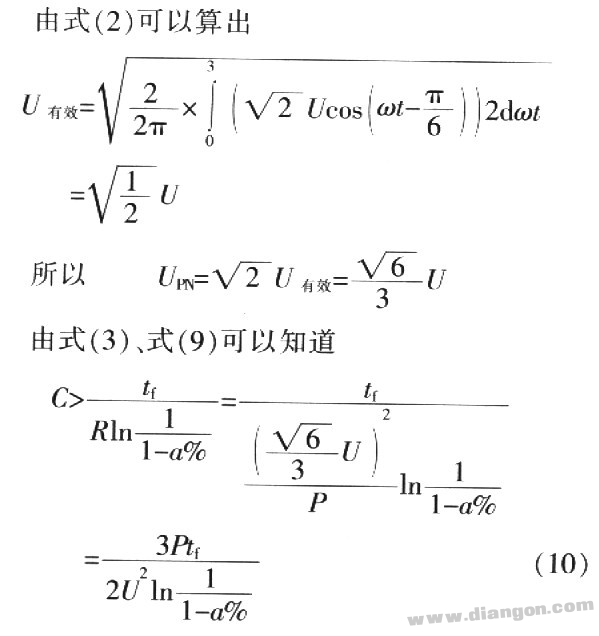
Although the alternating current can be converted to direct current by the rectifying circuit, in the three-phase circuit, the direct current voltage or current contains a voltage or current ripple having a frequency six times the power supply frequency. In addition, the inverter inverter circuit will also generate ripple voltage or current due to output and carrier frequency, etc., and in turn affect the quality of the DC voltage or current. Therefore, in order to ensure that the inverter circuit and the control circuit can obtain a high-quality DC voltage or current, the DC voltage or current must be filtered to reduce the voltage or current ripple. l Calculation of three-phase inverter DC intermediate circuit electrolytic capacitor 1.2 Three-phase input and rectified voltage waveform Three-phase input line voltage 220V and the rectified voltage waveform are shown in Figure 2. In Fig. 2, Ua, Ub, and Uc are three-phase three-wire three-phase input phase voltages; uc is a capacitor voltage, and ur is a voltage when no capacitor is applied after rectification. Example: Take the three-phase 220V series 2.2kW variable device as an example to calculate the electrolytic capacitor required for its DC intermediate circuit. Substituting the above data into equation (9) yields C>1036.56μF 2 Single-phase inverter DC intermediate circuit electrolytic capacitor calculation Here, the value of the single-phase input line voltage is still the same as the above three-phase input. 3 Experimental results 4 Conclusion The design of the inverter hardware loop is to take into account the use of good performance components while paying more attention to minimize costs. Capacitance values ​​that rely on experience generally leave a large margin, indirectly increasing costs. The algorithm for electrolytic capacitors in DC intermediate circuits is feasible and reliable in practical applications. Through theoretical calculations, the designer can select the corresponding filter capacitor according to the load of different voltage levels and different powers. This algorithm has been applied in practice and has achieved certain economic benefits. Monitor Stand For Computer Screens Shenzhen ChengRong Technology Co.,Ltd. , https://www.dglaptopstandsupplier.com
The DC link refers to the filter circuit inserted between the DC power supply and the inverter circuit. The difference in structure will have different effects on the performance of the converter: when the inductive structure is used, the input current ripple is small, similar to the current source. Nature; where a capacitive structure is used, the input terminal voltage ripple is small, similar to the nature of the voltage source.
For a voltage-type inverter, the output of the rectifier circuit is a DC voltage, and the DC intermediate circuit filters the voltage through a large electrolytic capacitor. For the current-type inverter, the output of the rectifier circuit is a DC current, and the intermediate circuit is This current is filtered by a large inductor.
1.1 Inverter and DC intermediate circuit structure block diagram The inverter and DC intermediate circuit structure diagram is shown in Figure 1. 

1.3 Analysis process
1.3.l Calculation of voltage after rectification 
For the three-phase three-wire input line voltage is 220V series inverter (hereinafter referred to as 220V series) U=220V; for 440V series, U=440V. 
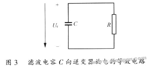
1.3.2 Calculation of equivalent resistance is convenient for calculation. For an inverter with output power P, the impedance of the input side of the DC side is equivalent to a pure resistance R. 
1.3.3 Analysis of charge and discharge process of capacitors Since the DC voltage after rectification fluctuates, assuming that the fluctuation amplitude of ur is a%, then ![]()
Assuming that the circuit is already in a steady state, the voltage across the capacitor is as shown in Figure 2. At time t2, the capacitor voltage reaches its maximum value. After the power supply voltage is lower than the capacitor voltage, the capacitor begins to discharge; at time t3, when the power supply voltage drops to the minimum value, the capacitor voltage is still greater than the power supply voltage, and the capacitor continues to discharge: at time t4, the power supply voltage is exactly equal to the capacitor voltage, and thereafter the power supply is given Capacitor charging. At time t4, the capacitor voltage is equal to UPV (1-a%). (http://)
1.3.4 Calculation Process As can be seen from Figure 2, the discharge time of the capacitor is tf=t4-t2 


It is known that U=220V, UPN=310V, f=50Hz, and a =5 is assumed. 
Considering the actual capacitance value, you can choose to use three 470μF electrolytic capacitors in parallel.
Since the voltage waveform after rectification of the three-phase inverter is six pulses, the single-phase inverter has only two wave heads. 
For single phase 220V series O. 4kW series inverter comes 
So for the single phase 220V series O. For 4 kW inverters, use three 220μF electrolytic capacitors in parallel.
(1) Three-phase input 220V series 2.2kW inverter Under the condition that the carrier frequency is 14.5 kHz, the load is full load, and the DC link uses three 470μF electrolytic capacitors in parallel, the maximum and minimum values ​​of the measured capacitor voltage are respectively 312V and 299V, the average is 305V, the ripple factor is about 4.26%;
(2) Single-phase input 220V series O. Under the condition that the carrier frequency is 14.5 kHz, the load is full load, and the DC link uses three 220μF electrolytic capacitors in parallel, the maximum and minimum capacitance voltages are 308V and 294V, respectively, and the average value is 301V. The ripple factor is approximately 4.65%.