Design of an analog divider and simulation verification of CMOS process
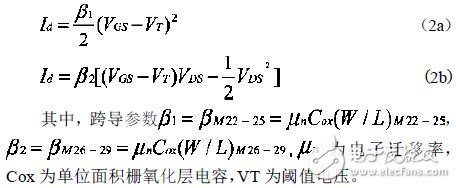
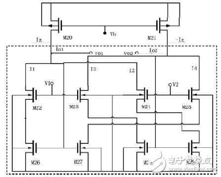
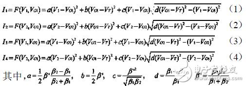
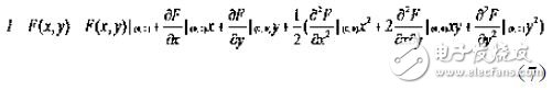
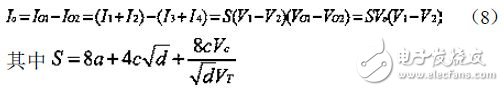
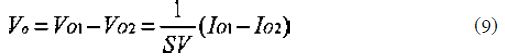
In this paper, an analog divider is designed. Based on the analysis and discussion of its working principle, the CSMC0.5um CMOS process is used to simulate the Cadence Spectre. The simulation results verify the theoretical analysis. 1 circuit design and analysis Figure 1 CCII circuit structure The analog divider is powered by a single supply +5V and consists of two parts. The first part is the second generation current transmitter CCII, and Figure 1 is the CMOS CII circuit. Transistors M3 and M4 form a differential amplifier. The output of the amplifier is transmitted to the Y terminal through transistor M8, and the current mirror formed by transistors M1 and M2 is the active load of the differential amplifier. Assuming that transistors M1 and M2, M3 and M4, M9 and M10 are matched, transistors M5, M6, M7 and M11 form a bias current mirror that provides bias current for each of the three branches, and I7 = I11. The current mirror composed of transistors M1 and M2 forces the drain and source currents of transistors M3 and M4 to be equal, so that Vgs3=Vgs4, and transistors M3 and M4 are source-coupled pairs, so the gate voltages of transistors M3 and M4 are equal, that is, Vx=Vy. . Transistor M8 acts as a source follower and provides a low output impedance at the Y terminal. If Vy "0" and R is the Y-terminal resistance, the current flowing from the Y terminal is iy=Vy/R, and the drain current of the transistor M8 is (I7+iy), which is reproduced by the action of the current mirrors M9 and M10. To the Z end. Since I11=I7, the current flowing out of the Z terminal is equal to the current at the Y terminal, that is, iz=iy. Transistors M12-M17 form a cross-coupled current mirror that replicates the current (I7+iy) to the Z port. Since current I16 follows current I7, current iz flows in the opposite direction, ie iz=-iy. Thus, it can be seen that the CCII circuit can be implemented: The second part of the voltage-current conversion circuit is shown in Figure 2. Transistors M20, M21 provide a constant and equal current source. Transistors M22-M25 operate in the saturation region and M26-M29 operate in the linear region. Ignore the body effect, the leakage current Id: Figure 2 voltage and current conversion circuit The circuit in the dotted line in Fig. 2 can be divided into four branches, which are composed of transistor pairs (M22, M26) (M23, M28) (M24, M29) (M25, M27). The voltages V1 and V2 are input signals. According to equations (2a) and (2b), we can get the relationship between current and voltage of four branches: Equations (3)-(6) are expanded according to the Taylor series, and as shown in (7), they are expanded at the (0,0) point second order: After integrating the path, the total differential output current is: So, define the differential input V=V1-V2 And the differential input current: By equations (9), (10), (11), and (1)
RIMA UN series 12V AGM batteries represent the zenith of sealed lead acid battery technology. Fabricated with ultra-high purity lead, these 12V Rechargeable batteries set the standard in performance and durability, serving a multitude of applications with unmatched efficiency.RIMA 12V AGM Battery is designed for diverse applications, from emergency backup and renewable energy systems to UPS and recreational vehicles. Their robust construction and reliable performance make them suitable for a wide array of uses, ensuring uninterrupted operation in critical situations.
RIMA UN series 12V AGM batteries are not just about providing power; they are about delivering reliable, safe, and efficient energy solutions across a variety of applications. With RIMA, you choose more than a battery; you choose a partner committed to powering your success in the digital age and beyond. 12v AGM Batteries,12v AGM Battery,12V lead acid battery,12V Rechargeable batteries,12V VRLA Batteries OREMA POWER CO., LTD. , https://www.oremabattery.com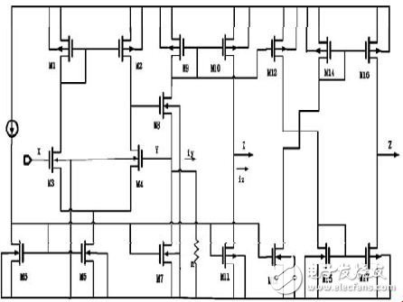

Innovative AGM Technology:
At the heart of RIMA UN Series 12V VRLA Batteries is the advanced Absorbent Glass Mat (AGM) technology. This technology ensures safety and flexibility in installation by absorbing the electrolyte in a fiberglass separator. It effectively eliminates the risk of leakage, provides excellent resistance to vibration and shock, and maintains a low self-discharge rate. This versatility makes them ideal for both long-term storage and demanding usage scenarios.
Key Features of RIMA UN Series 12V lead acid battery:
- Extended Lifespan: Designed to last 5-12 years at 25℃, these batteries offer exceptional longevity.
- Spill-Proof Design: The non-spillable construction of AGM technology guarantees safety and ease of use.
- Zero Maintenance: These batteries are maintenance-free, adding to their convenience and reliability.
- High-Quality Raw Materials: The utilization of high-purity lead ensures a longer lifespan and minimal self-discharge.
Compliance and Quality Assurance:
RIMA 12V AGM batteries adhere to global standards, including IEC, BS, JIS, and EU regulations. UL and CE certifications, along with ISO45001, ISO 9001, and ISO 14001 certifications of our production facilities, reflect our commitment to quality and environmental stewardship.
Applications of RIMA UN Series 12V Rechargeable batteries:
- Power for UPS Systems: Ideal for providing stable and uninterrupted power in UPS setups.
- Emergency and Backup Power: Dependable in emergencies and power outages.
- Control Systems Support: Crucial for the continuous operation of control systems.
- Communication and Security Systems: Essential for maintaining communication and security infrastructures.
- Electric Power Systems: Suitable for EPS applications, offering consistent and robust power.