PCB design for battery charger circuit
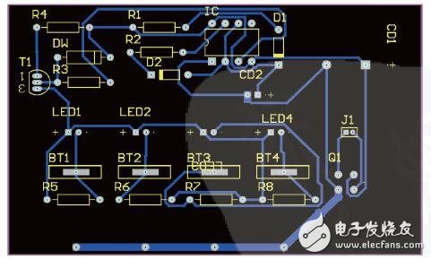
1 Introduction to Protel Software With the rapid development of electronic information technology, the PCB (printed circuit board) of hand-designed electronic products can no longer meet the needs of the development of electronic technology. We must use the computer to complete the design of the PCB. It is not only fast, accurate, but also greatly reduces the labor intensity of engineers and technicians. There are many kinds of software involved, and Protel is one of the more classic ones. Protel is a circuit-aided design system from AlTIum. It is the first board-level design system that integrates all design tools, including schematic design, PCB design, circuit simulation, and PLD design. Its earliest version was the TANGO software package, which was later developed into Protel for DOS, Protel for Windows, Protel 98, Protel 99 SE, Protel DXP and Protel 2004. As the version continues to evolve, it is becoming more powerful. Compared to other versions, Protel 2004 adds many new features that make operation simpler and more automated, making it easy to perform complex board designs. 2 PCB design PCB is the abbreviation of English Printed Circuit Board, translated as printed circuit board, referred to as circuit board or PCB board. The printed circuit board is printed and fabricated into a conductive circuit and component package. Its main function is to realize the fixed installation of the electronic components and the electrical connection between the pins, thereby realizing various specific functions of the electrical device. Making the correct, reliable, and beautiful printed circuit board is the ultimate goal of circuit board design. The general process of PCB design includes: pre-production preparation, PCB component lead package, new PCB file, planning board, load component package and network, layout, routing, DRC design rule check, etc. 3 Ni-MH Battery Charger PCB Design The Ni-MH battery charger is an electronic product that is common in our lives. The basic steps for designing a printed circuit board (PCB) for this circuit with Protel 2004 are as follows. 3.1 Creating a project file To facilitate the management of each design file and the seamless connection and synchronization between them. In Protel 2004, using project files for management, you first need to create a project file, and then create or add each design file under the project file. 3.2 Create a schematic file and complete the schematic design of the battery charger circuit The schematic diagram of the Ni-MH battery charger circuit is shown in Figure 1. Figure 1 battery charger schematic 3.3 Create PCB files and plan There are two ways to create a PCB file in Protel 2004: create it with the File menu and create it with the wizard. Note that the PCB file created with the wizard is not in the project file. It must be placed in the project file after creation, otherwise it will be There is no way to proceed. According to the composition of the charger circuit, the shape of the board is first planned to be a rectangle, and the size of the board is determined to be 2400 mil & TImes; 1300 mil according to the number of components, and the single layer wiring is designed as a single panel. 3.4 Load component pin package and network and component layout All components in this circuit are in the form of a jack package. In addition to the battery pack's positive package, other components are packaged in the standard package of the Protel 2004 library. We need to set the package for the positive side of the battery pack according to the actual circuit. First, create your own component package library. The library is created as shown in BT1-BT4 in Figure 2, and then this package is set as the package of the battery pack. Figure 2 battery charger PCB diagram The component layout can be performed by first automatically arranging and then manually adjusting. Note that the transformer is not placed on this board. When layout, pay attention to the arrangement and distribution of components should be reasonable and uniform, and strive to be neat, beautiful, and meet the structural requirements of circuit structure. 3.5 Setting wiring rules and wiring The so-called "wiring" is to use the printed wires to complete the connection relationship of the components in the schematic. After completing the layout of any component board, the next step is to connect the components with wires to make them electrically, thus forming a complete circuit board. In Protel 2004, the wiring rules must be set first to meet the electrical requirements such as safety principles. According to the actual requirements of the charger circuit, the safety spacing is 10 mil, the top wiring, the common line width is 10 mil, the power line is 20 mil, and the ground line is 30 mil. The wiring is automatically routed, and the undesired place can be manually modified. Under the premise of meeting the electrical requirements such as safety principles, the wires should be streamlined, as short as possible, and bend as little as possible, so that the wires are simple and clear. In addition, the design of the wiring should consider whether the assembly is convenient or not. Finally, the board is required to be beautiful and economical. The good PCB board layout is beautiful and the work is fine. It looks like a piece of art. 3.6 DRC design rule checking and error elimination. After the circuit board design is completed, in order to ensure that the design work performed meets the requirements, the inspection work can be automatically performed by the computer, that is, the DRC design rule check. After the check is completed, the message dialog box will pop up, and according to this information prompt, the design will be modified until there are no errors. The PCB design work of the circuit is completed, and the designed charger PCB file is shown in Figure 2. Finally, you can print out the output drawings and reports, and carry out the corresponding follow-up work such as actual board making. 4 summary PCB design with Protel 2004 software is easy to operate and highly automated. The Ni-MH battery charger PCB design has the commonality of PCB design and also has certain characteristics. To design a perfect charger PCB, a lot of experience is required. With the development of electronic technology, electronic circuits are becoming more and more complex, requiring designers to continuously improve the design level and design more PCB boutiques. High Frequency AC Power Supplies High Frequency Variable frequency AC power supply converts AC electric to pure sine waveform by through AC – DC – AC conversion, which is different from variable frequency speed controller and common AC voltage regulator.
High Frequency AC Power Sources, AC High Frequency Power Supplies, High Frequency AC Sources, AC Power Sources, AC Power Supplies Yangzhou IdealTek Electronics Co., Ltd. , https://www.idealtekpower.com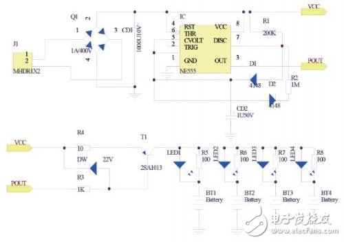


VFP-H series variable frequency power supply is manufactured under SPWM mode; it is designed by MOSFET module as active component, and adopts other technologies as digital frequency division, D/A conversion, instantaneous feedback and sinusoidal pulse width modulation to make the capacity of single unit up to 150KVA. Isolated transformer used to enhance total stability, strong load applicability, high quality output waveform, and simple operation, small size and light weight. In addition, this power supply has many protective functions against short circuit, over current, over load and over heat to ensure proper operation.
Comparing to traditional frequency inverter power supply, our inverter power supply removes the transformer and frequency converter, by using pure high-frequency conversion technology, with built-in by AC/DC and DC/AC parts, our AC inverter power supply could give stable AC output with prefect output precision.
Because, our new technology does not need transformer for conversion and isolation, the power supply size can be reduced within the same output power rating, and not limited by the transformer, output frequency could reach 15 ~ 1Khz continuously adjustable.