Discussion on design ideas of uninterruptible power supply (UPS)
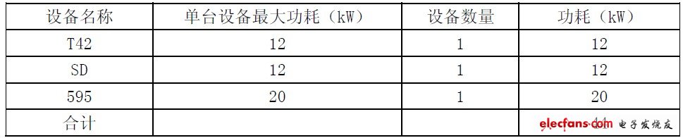
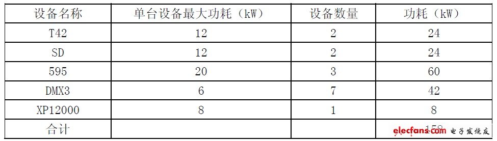
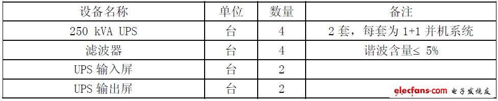
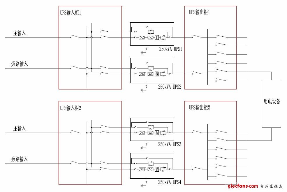
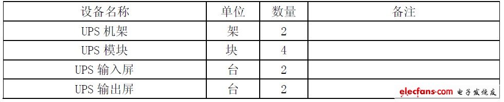
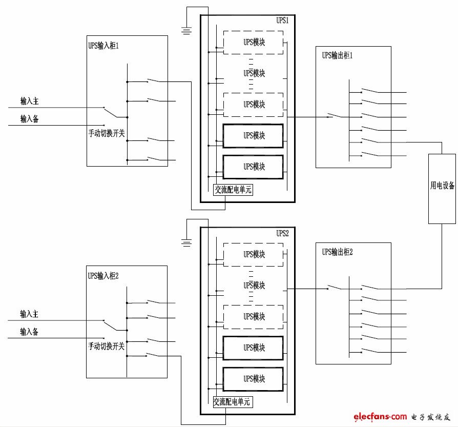
With the rapid development of the communications industry, data services and IT services are also showing an increasingly rapid development trend. After the data service adopts the blade server, the integration degree is high. At present, the data room has become the computer room with the highest power consumption of the operator. The power supply of the data device has become the most concerned issue for operators. How to better provide high quality and reliable data devices. The power supply guarantee is an urgent issue to be explored. This paper has carried out some analysis on the design problem of uninterruptible power supply (UPS), and after comparison and reached a conclusion. 1. Existing UPS design plan When the data device is initially built, the AC power supply is mainly used, so most of the UPS devices are configured to supply power. When configuring a UPS device, due to the need to expand the capacity of the power device, and the early UPS device cannot be expanded, it can only be configured according to the data device forward load. This will result in a high initial construction investment. After the system is completed and put into production, the equipment utilization rate is low. Take the BOSS system of a hub building as an example. In 2006, the hub building was built with a new BOSS system. The equipment load situation is shown in Table 1 and Table 2. Table 1 New equipment load situation in this period Table 2 Long-term equipment load situation According to the above equipment load, the UPS output power factor provided by the UPS manufacturer is 0.8 (the power factor is the ratio of active power to apparent power, expressed as COSΦ. In the AC circuit, the voltage multiplying current is the apparent power, and A part of the power that is used for work, that is, the active power is less than the apparent power). Considering the power factor of the load (considered by 0.8), when the power factor of the load is inconsistent with the output power factor of the UPS, care should be taken to ensure that the capacity of the UPS can provide sufficient useful power and useless power to the load. The capacity of the UPS. According to the calculation, a 250kVA UPS needs to be configured. At that time, considering the importance of the support system, a double busbar configuration was adopted, that is, two sets of 250 kVA UPS devices were configured, and each set was considered as a 1+1 parallel system. Since the harmonic components of the UPS device itself are difficult to control to the required values, a filtering device must be configured to reduce the harmonic components. See Table 3 and Figure 1 for UPS equipment configuration and power supply system. Table 3 Device Configuration Table Figure 1 Traditional UPS (1+1) double bus system diagram 2, modular UPS design Due to the limitations of traditional UPS design and some problems with the device itself, today a rack-mounted modular UPS is quietly revolutionizing, and its introduction will inevitably lead to a new revolution in uninterruptible power supplies. There are two types of modular UPS structures: one is a power modular UPS, and the other is a fully modular UPS. The power modular UPS consists of a rack plus power module, and the power module includes a traditional UPS. Rectification, filtering, charging, inverter, etc., but the static bypass and the system part of the monitoring and display share a rack, each module independently controls the parallel operation, the display control module on the rack only serves as the user switch UPS host and Networked monitoring platform. The fully modular UPS consists of a rack and a single module. Each unit module is equipped with the entire UPS power supply and control circuit, including rectifier, inverter, static bypass switch and auxiliary control circuit, CPU main control board. Each UPS module has an independent management display. We also rely on the previous case, assuming a fully modular UPS device, the configuration scheme is as follows: According to the recent load, combined with the long-term development needs, the UPS system is also considered in the double bus configuration. Two sets of UPS devices can be configured. Each set only needs to be configured with 2 UPS modules (50kVA each) to meet the needs of this period. 1+1 redundancy mode configuration, one module for the main module and one module for redundancy. If one of the modules fails, it will automatically leave the system, and other modules continue to supply power to the load to ensure the normal operation of the system; The modular UPS system adopts the double busbar power supply mode. The main equipment AC power distribution screen is connected to each of the two sets of UPS output screens. When one set of UPS fails, the other set of UPS bears all the load power to ensure the safety of the equipment. run. After adopting the modular UPS equipment, the harmonic content ≤ 5% can be met without configuring the filtering equipment. The UPS equipment configuration and power supply system are shown in Table 4 below and Figure 2. Table 4 Device Configuration Table Figure 2 Modular UPS (1+1 module redundancy) dual bus system diagram Hall Sensor,Hall Current Sensor,Current Sensor Hall Effect,Open Loop Hall Effect Current Sensor Zibo Tongyue Electronics Co., Ltd , https://www.tongyueelectron.com