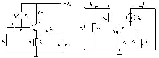
Emitter follower circuit
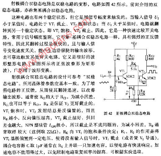
1. Input impedance From the circuit in the above figure (b), the input impedance from the end of 1, 1` to the right is: Ri = Ui / Ib = rbe + (1 + β) ReL Figure 2 is a bootstrap follower, its characteristics are: Follow WeChat Download Audiophile APP Follow the audiophile class related suggestion Emitter coupled bistable circuit diagram Features and applications of emitter output & nb ... Emitter output characteristic measurement 1. Experimental purpose 1. By comparing with the common-emitter amplifier, master the main characteristics of the emitter output. 2. Study ... Emitter follower '+ data.data.username +' '; dom + ='
The 7-inch tablet can be used as the golden size of a tablet computer. It is small and portable. It can be used at home and outdoors. You can browse the web, watch videos and play games. It is a household artifact. Although the size of the 7-inch tablet is inclined to the tablet, the function is more inclined to the mobile phone, so it can also be used as a substitute for the mobile phone. Compared with other sized tablets, the 7-inch tablet has obvious advantages in appearance and weight. Both the body size and the body weight have reached a very reasonable amount.
1.In appearance, the 7 inch tablet computer looks like a large-screen mobile phone, or more like a separate LCD screen.
2.In terms of hardware configuration, the 7 inch tablet computer has all the hardware devices of a traditional computer, and has its own unique operating system, compatible with a variety of applications, and has a complete set of computer functions.
3.The 7 inch tablet computer is a miniaturized computer. Compared with traditional desktop computers, tablet computers are mobile and flexible. Compared with Laptops, tablets are smaller and more portable
4.The 7 inch tablet is a digital notebook with digital ink function. In daily use, you can use the tablet computer like an ordinary notebook, take notes anytime and anywhere, and leave your own notes in electronic texts and documents.
7 Inches Tablet Pc,Quad Core Tablet 7 Inch,7 Inch Gaming Tablet,Supersonic Tablet 7 Inch Jingjiang Gisen Technology Co.,Ltd , https://www.jsgisentec.com The emitter follower (also known as emitter follower, referred to as emitter follower or follower for short) is a common-collector circuit. See the figure below. It inputs the signal from the base and outputs the signal from the emitter. It has the characteristics of high input impedance, low output impedance, and the phase of the input signal and the output signal are the same 
In the formula: ReL = Re // RL, rbe is the input resistance of the transistor. For low-frequency low-power tubes, its value is: rbe = 300 + (1 + β) (26 mV) / (Ie mV)
In the circuit of (b) above, if the input impedance from the b and b 'ends to the right is Ri = Ui / Ii = Rb // Rio. As can be seen from the above equation, the input impedance of the transmitter-follower is higher than that of the common emitter The input impedance rbe of the pole circuit is high (1 + β) times.
2. The output impedance will be Es = 0, and the output impedance from the e and e 'in the above figure (C) is: Ro = Uo / Ui = (rbe + Rsb) / (1 + β), where Rs = Rs // Rb,
If the output impedance from the output terminal 0, 0 'to the left is Ro = Ro // Reo
3. The voltage amplification factor is obtained according to the equivalent circuit of (b) above: Kv = Uo / Ui = (1 + β) Rel / [Rbe + (1 + β) Rel],
In the formula: Rel = Re // RL, when (1 + β) Rel >> rbe, Kv = 1, usually Kv <1.
4. The current amplification factor is calculated according to the equivalent circuit of (b) above: KI = Io / Ii = (1 + β) RsbRe / (Rsb + Ri) (Re + RL)
In the formula: Rsb = Rs // Rb, Ri = rbc + (1 + β) Relo Generally, the emitter follower has current and power amplification effect. Second, the practical circuit of the follower The following figure is a circuit used by a high-frequency amplifier. The signal is output by a coaxial cable. The characteristic impedance of the cable is generally 50 ohms or 70 ohms, so the impedance conversion must be achieved through the follower BG2. 
1. Bootstrapping Because the potential at the lower end of R3 rises with the rise of the potential at the upper end, it is called a bootstrap. The bootstrap effect makes the AC voltage drop across R3 zero. Therefore, for AC, R3 is equivalent to an open circuit, thereby avoiding the defect that the bias circuit reduces the input impedance.
2. High input impedance In order to increase the effective input impedance of the transistor as much as possible, BG1 and BG2 are used to form a composite tube circuit. At this time, β = β1β2, which greatly increases the total input impedance. Because the input impedance Ri = Rbe + (1 + β) Reo The input impedance of this circuit is 2 megohms, 
Figure 3 is a series-connected follower, its characteristics are: (1) similar to Figure 2, the AC voltage across R4 has a bootstrap effect; (2) BG2 uses a common base connection method, so that Ic2 has a constant current function The AC impedance RAB at the two points of B and B is also greatly increased, thereby improving the input impedance of the follower. 
Figure 4 is a complementary follower. The characteristics of the circuit are: (1) Because the two transistors supply the load current in turn, the power consumption of each tube is only about (12-20)% of the output power, and the efficiency is high; ( 2) Both transistors are output from the emitter, and their output impedances are basically the same, so the positive and negative half waves of the output waveform are symmetrical; (3) Since the input signal is coupled to the base of the transistor through BG3 or BG4, DC signals can be followed. Its following range is about ± 5 volts 


'+ data.username +'
'+ data.username +'
'; dom + ='
'; $ (' # follow_list '). append (follow_user);} if (data.status == "failed") {alert (data.msg);}});} else {// Unfollow if ($ ( this) .attr ('id') == 'cancelFollow') {$ .post ('/ d / user / cancelFollow', {tuid: article_user_id}, function (data) {// Data format returned: if (data .status == "successed") {follow_wrap.html ('Follow'). attr ('id', 'follow'). css ('background', '# f90'); $ (". followNum strong"). html (-getFollowNum); $ ('# follow_list .face'). each (function () {var target_uid = $ (this) .attr ('data-uid'); if (target_uid == now_uid) {$ ( this) .remove ();}})} if (data.status == "failed") {alert (data.msg);}}); return false;}}});});}); / * var myface = "{$ _super ['uid'] | avatar}"; var myname = "{$ _super ['username']}"; var article_id = {$ article ['id']}; var article_user_id = {$ article ['mid']}; // Article author ID $ (function () {<notempty name = "clearnum"> // Reduce the number of reminders var count = parseInt ($ ("# noticeCount"). html ()); count = count-{$ clearnum}; $ ("# noticeCount"). html (count); if ( count