Smart home control system based on Qt / Embedded touch screen
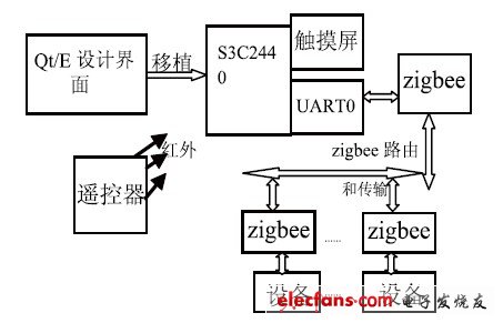
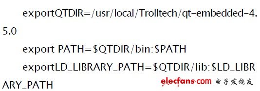
1 Introduction With the improvement of the quality of life, home intelligence has become a mainstream in today's era. How to better design the overall control of smart home becomes more and more important. Due to the rapid development of ARM and touch screens, it has become possible to use a better GUI to achieve friendly interface control; at the same time, due to the wide application of zigbee unlimited transmission technology, through the design of zigbee protocol networking, ARM can easily pass through the serial port driver The program realizes the control of the smart home; at the same time, through the learning of the identification code of the universal remote control by ARM, the multi-functional application of ARM on the smart home and the integrated control of the smart home are realized. 2 System design overview The block diagram of the design structure based on the embedded smart home is shown in Figure 1. It mainly includes the following parts. Qt / E and linux system, ARM9 microprocessor, zigbee module, voice module, GSM module, serial port and network module and universal remote control. Figure 1 Block diagram of smart home design structure ARM9 microprocessor adopts Samsung S3C2440 CPU development board, the system chooses embedded Linux system, its kernel uses 2.6.25.8 kernel, nandflash uses 256M memory. And because the arm kernel integrates a variety of peripheral control module drivers, it is necessary to tailor it, the serial port is used to connect the zigbee module. Zigbee uses TI's CC24430 radio frequency chip. Zigbee has significant wireless transmission functions such as low cost, low consumption, and many network nodes. Therefore, one zigbee can be used as a route to transmit multiple zigbee through one zigbee to realize zigbee. The network of the network also effectively extends the transmission distance of zigbee. The network module uses CS8900A, and connects to the router to achieve remote login. 3 System software design and implementation The system uses linux as the operating system. Firstly, the graphical interface is designed based on Qt / Embedded, and then the cross-compilation environment is established on the host machine, and the yaffs operating system is produced. Finally, the embedded linux system is transplanted to the ARM9 development board. By designing GUI interface, the system realizes the integrated control of smart home through touch screen [1]. The software part of the article includes transplantation of embedded linux operating system, system interface design, serial port driver and zigbee networking design. During the transmission of ARM9 and zigbee, there is a unit-side interface setting for smart home. In order to distinguish it from the transmission between different families, first of all, ARM9 will have a host ID set for each family. In the intelligent control of a home, eight ports are designed for the zigbee of the routing function, each port has an ID number, and then the remaining zigbee connected to the routing separately transmit information by receiving their ID numbers, and finally, these zigbee are separately Set the respective device numbers, so that the interference is removed and the smart home can be controlled independently. 3.1 The establishment of touch screen and Qt / Embedded cross compilation environment Before establishing a cross-compilation environment, the Linux system must be transplanted. The Linux system transplantation mainly includes BootLoad transplantation, kernel transplantation and cropping, and file system transplantation [2]. This article chooses u-boot as the bootloader for BooLload. Because of its openness, the Linux kernel can easily be transplanted and tailored. File system This uses the yaffs root file system. The establishment of the cross-compilation environment of the touch screen and Qt / Embedded is a key part of the Linux system transplantation. The steps are as follows. The first step is to perform touch screen calibration. TIslib-1.4 is used as the touch screen calibration in the design. It is divided into two steps: (1) Compile TIslib and generate a correction file. (2) Download the calibration file and library file to the arm board to achieve five-point calibration. The compilation process is as follows. The second step is Qt / E cross compilation. In the design, Qt / E uses qt-embedded-linux-opensource-src-4.5.0. At the same time, in order to facilitate program development, the X86 version and the ARM version need to be installed. First use the x86 version and qvfb development on the PC, and then use ARM cross compilation to run on the development version after completion. So you need to unzip it once and then rename it to qt-embedded-linux-opensource-src-4.5.0-x86; unzip it again and rename it to qt-embedded-linux-opensource-src-4.5.0-arm.Qt The compilation process of / E is as follows. Finally, set the cross-compilation environment variables, enter the system control platform vi / etc / profile. Write the environment variables as follows: The handheld addresser is used to program the address of the monitoring module offline. When in use, connect the two output wires of the handheld encoder to the communication bus terminal (terminal label 1, 2) of the monitoring module, turn on the black power switch on the right side upwards, and press "ten Add", [Subtract ten", [Add one place" and [Subtract one place" to program the address. Position Encoder,Magnetic Rotary Encoder,Hybrid Encoder,Channel Encoder Changchun Guangxing Sensing Technology Co.LTD , https://www.gx-encoder.com