Single-chip Microcomputer Implementation Scheme of Temperature Measurement System of PC Serial Communication
Abstract: Introduces the working principle and design method of the temperature control system with AT89S52 single chip microcomputer as the core. The system collects the temperature signal from the chip DS18B20 and transmits it to the microcontroller, displays the temperature value on the spot through the peripheral device LCD1602, and designs the host computer program to obtain the temperature in real time through serial communication. System design includes hardware circuit design and software design. The single-chip computer program adopts C51, and debugging is completed in the KEIL development environment; the PC background software is completed with VB6.0. The design flow chart of front and back end software is given. Finally, the physical map of the design and the temperature display results of the collected front and background are given. Temperature is one of the main controlled parameters in industrial control. The traditional methods of temperature detection and control mostly use thermal resistance and thermocouple as temperature sensing elements, and the output of this analog temperature sensor is an analog signal, which must go through A / D. The conversion link can only be interfaced with microprocessors such as single-chip computers after obtaining digital signals, which makes the hardware circuit structure more complicated, poor anti-interference, troublesome wiring and high cost. In response to the above problems, the design proposes a temperature measurement system based on Dallas Semiconductor ’s digital temperature sensor DS18B20 [1-2] and ATMEL ’s AT89S52 single-chip microcomputer, which can be connected to a PC system for real-time display via a serial port. The system is installed Simple, high reliability, suitable for on-site temperature measurement in harsh environments. 1 System configuration The temperature measurement system is composed of microcontroller, temperature acquisition, serial communication, LCD display and host computer display, as shown in Figure 1. Figure 1 System composition The data acquisition process is as follows: the single-chip microcomputer AT89S52 acquires the temperature value collected by the temperature sensor DS18B20, transmits it to the LCD1602 after processing, and uploads it to the upper computer through serial communication for display by the upper computer. 1.1 DS18B20 digital temperature sensor DS18B20 temperature sensor is an improved intelligent temperature sensor introduced by American DALLAS semiconductor company. Compared with traditional thermistors and other temperature measuring elements, it can directly read the measured temperature and can be read by simple programming according to actual requirements. Take 9 to 12 digital temperature values. The performance characteristics of DS18B20 are as follows: ①Wider voltage range (3.0 ~ 5.5 V), can be powered by data line in parasitic power supply mode; ②Unique single-wire interface. When connecting with the microprocessor, only one line is needed to achieve two-way communication; ③DS18B20 supports multi-point networking function; ④DS18B20 does not need any peripheral components in use, all sensing elements and conversion circuits are integrated in an integrated circuit shaped like a triode; ⑤Temperature range -55 ℃ ~ + 125 ℃, accuracy is ± 0.5 ℃ at -10 ~ + 85 ℃; ⑥ The programmable resolution is 9 ~ 12 digits, and the corresponding resolutions are 0.5 ℃, 0.25 ℃, 0.125 ℃ and 0.062 5 ℃, which can realize high-precision temperature measurement; ⑦The conversion time is 93.75 ms (9 digits) and 750 ms (12 digits), which is enough for the general real-time temperature measurement system; ⑧The measurement results directly output digital temperature signals, which are serially transmitted to the CPU by Dan bus, and can also transmit CRC check codes, which have strong anti-interference and error correction capabilities; ⑨Negative pressure characteristics: when the power polarity is reversed, the chip will not be burned due to heat, but it will not work properly. 1.2 RS_232 serial communication standard RS_232C is the most widely used standard bus for asynchronous serial communication developed by the American Electronics Industry Association (EIA). This standard is suitable for communication with a data transmission rate in the range of 0 ~ 20Kbps. It has become the interface standard for data terminal equipment DTE and computer and data communication equipment DCE. It is the most widely used serial interface in the PC and communication industry. The working level is defined as follows: For data (logic "1" level is lower than -3V; logic "0" level is higher than + 3V). For control signals ("signal valid" level is higher than + 3V, "signal invalid" level is lower than -3V). In actual work, the level should be ± (3 ~ 15) V. The 9-pin function of its serial port has its fixed definition. In this design, only two data lines RXD and TXD can be used. 1.3 AT89S52 AT89S52 is a low-power, high-performance 8-bit microcontroller with CMOS technology, which carries 8K in-system programmable flash memory. Fully compatible with 80C51 product directives and pins. So that it can provide highly flexible and ultra-effective solutions for many embedded control application systems. The AT89S52 also contains: 256 bytes of RAM, 32-bit I / O lines, watchdog timer, 2 data pointers, three 16-bit timers / counters, a 6-vector 2 level interrupt structure, full-duplex serial Mouth, on-chip crystal oscillator and clock circuit. In addition, AT89S52 can be reduced to 0 Hz static logic operation and supports 2 software selectable power saving modes. In idle mode, the CPU stops working, allowing RAM, timers / counters, serial ports, and interrupts to continue to work. In the power-down protection mode, the RAM content is saved, the oscillator is frozen, and all the work of the microcontroller is stopped until the next interrupt or hardware reset. 1.4 LCD1602 display module The liquid crystal display module has the advantages of small size, low power consumption, rich display content, ultra-thin and lightweight, etc., and is widely used in pocket instruments and low-power application systems. At present, the character liquid crystal display module is already the most commonly used information display period in the application design of the single chip microcomputer. The LCD1602 liquid crystal display module can display two lines of 16 characters each. The character generator ROM comes with numbers and English letters and some special symbols. Character library, no Chinese characters. Using LCD1602, it is possible to establish the characteristics of eight 6 & TImes; 8 dot matrix custom fonts. It uses a single + 5V power supply, the peripheral circuit configuration is simple, the price is cheap, and it has a high cost performance. There are two kinds of LCD1602 drive methods: parallel port driver and serial port driver. The parallel port driver must occupy a lot of precious I / O interfaces of the microcontroller; and the serial port driver must be based on the idle of the microcontroller's UART interface. Its main functions are as follows: 40-channel dot matrix LCD drive, which can be selected as row drive or column drive, input / output signals: the output can generate 20 & TImes; 2 LCD drive waveforms; the input accepts serial data and control signals sent by the controller , Bias voltage (V1∽V6), display the measured frequency signal reading through the single-chip control. On-Grid Inverter converts DC power to AC power for feeding back to the grid. The frequency of the output voltage of the grid-connected inverter needs to be the same as the grid frequency (50 or 60Hz), which is generally achieved by the oscillator in the machine, and the output voltage will also be limited not to exceed the grid voltage. Modern high-quality grid-connected inverters can have an output power factor of 1, which means that the output voltage and current phases are the same, and the phase difference between them and the grid voltage is within 1 degree. There is a microprocessor in the inverter that can sense the AC waveform of the grid, and according to this waveform, generate voltage and send it back to the grid. However, the electricity sent back to the grid needs to have a certain proportion of reactive power, so that the power of the nearby grid is within the allowable limit. noon) its voltage may rise too high. on grid solar inverter, micro inverter on grid, 25 kw on grid inverter, on grid power inverter, 15kw on grid inverter Ningbo Autrends International Trade Co., Ltd. , https://www.aitsolarpanels.com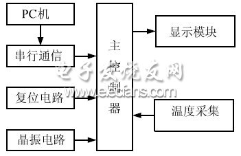
If the power of the grid is cut off, the grid-connected inverter needs to be disconnected from the grid quickly. This is a regulation of the National Electrical Code (NEC) in the United States to ensure that when the grid is out of power, the grid-connected inverter will not provide power to the grid, and at this time the workers who maintain the grid will not be electrocuted.
Properly configured, grid-tie inverters allow a home to use alternative energy sources that it generates itself (such as solar or wind power) without cumbersome wiring and without the need for batteries. If there is insufficient alternative energy, the insufficient part will still be provided by electricity from the grid.
Grid-connected inverters are widely used in household photovoltaic power generation systems, commercial and industrial photovoltaic power plants and other scenarios. By connecting to the grid, they help to achieve efficient use of renewable energy and reduce carbon emissions, promoting sustainable development and popularization of clean energy.