CAN bus technology and its application in automotive instrumentation
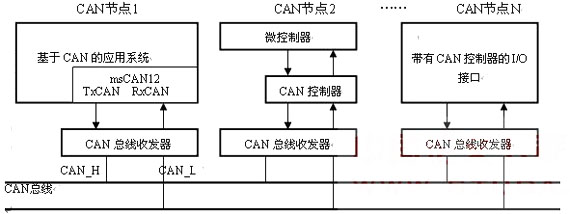
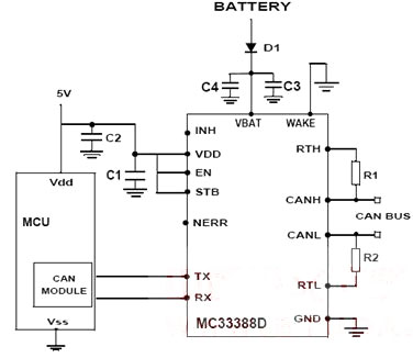
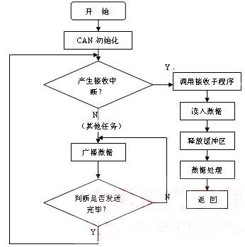
0 Preface This article refers to the address: http:// Control LAN (controllerareanetwork) is one of the most widely used fieldbuses in the world. It is a communication protocol developed by Bosch in Germany to solve the data exchange between many control and test instruments in modern automobiles. It is used as an automotive environment. In the microcontroller communication, information is exchanged between the vehicle electronic control unit ECUs to form an automotive electronic control network. For example, the engine management system, the gearbox controller, the instrumentation equipment, and the electronic trunk system are all embedded in the CAN control device. CAN is a multi-master serial communication bus. The basic design specifications require high bit rate, high immunity to electromagnetic interference, and the ability to detect any errors. When the signal transmission distance reaches 10Km, CAN can still provide data transmission rate of up to 50 kbit/s. It is a serial communication network that effectively supports distributed control or real-time control. CAN is used in applications ranging from high-speed networks to low-cost multi-line networks. In applications such as automotive engine control components, sensors, and anti-slip systems in the field of automation electronics, CAN's bit rate can be as high as 1 Mbps. The CAN network has the characteristics of fast reflection and high reliability, and is used in applications requiring real-time processing, such as car brake anti-lock system airbags. Today, this communication protocol has been widely used and has become a must-have device in modern car design. Mercedes-Benz, BMW, Volkswagen, Volvo and Renault have all used CAN as a means of networking controllers. 1 CAN bus characteristics and communication protocol 1.1 Features of the CAN bus The CAN bus is a serial communication network that effectively supports distributed control or real-time control. The communication medium can be twisted pair, coaxial cable or fiber. In automotive engine control components, sensors and other applications, the bit rate of the bus can be up to 1 Mbit/s. The CAN bus has the following main features: a. Non-destructive bus arbitration based on priority competition b. Can be transmitted by means of receive filtering multi-address frames c. With error detection and error frame automatic retransmission function d. Data transmission methods can be divided into data broadcast and remote data request 1.2 CAN bus frame format [1] The CAN bus communication protocol includes CAN2.0A and CAN2.0B. Their frame formats are as follows: (1) The CAN2.0A communication protocol specifies four different frame formats: The data frame is used for transferring data between nodes, and is the main body of the network information, and the frame format thereof includes: a frame start, an arbitration field, a control field, a data field, a CRC field, an ACK field, and a frame end. The length of the data segment can be programmed from 0 to 8 bytes. The remote frame is sent by the online unit and is used to request to send a data frame with the same identifier, the frame format is basically the same as the data frame, but there is no data field. ] The error frame error frame is a signal flag that detects a bus error and consists of two different fields. The first field is superimposed by error flags from different nodes, and the second field is the error delimiter. The CAN protocol uses CRC checking and provides corresponding error handling functions to ensure the reliability of data communication. The overload frame consists of an overload identifier and an overload delimiter indicating the internal overload status required by the logical link control layer and will be initiated by some error conditions of the media access control layer. The delay time used to extend the sequence of frames. (2) CAN2.0B communication protocol is divided into two frame formats: 1 standard frame The standard frame information is 11 bytes and consists of two parts: the information and data parts. The first 3 bytes are the information part. <1> Byte 1 is frame information. The 7th bit (FF) indicates the frame format. In the standard frame, FF=0; the 6th bit (RTR) indicates the type of the frame, RTR=0 indicates the data frame, RTR=1 indicates the remote frame, and the DLC indicates the data. The actual data length at the time of the frame. <2> Bytes 2 and 3 are message identification codes, and 11 bits are valid. <3> Bytes 4 to 11 are the actual data of the data frame, and are invalid at the time of the remote frame. 2 extended frame <1> The extended frame information is 13 bytes, including two parts, information and data parts. The first 5 bytes are the information part. Byte 1 is frame information. The 7th bit (FF) indicates the frame format. In the extended frame, FF = 1; the 6th bit (RTR) indicates the type of the frame, RTR=0 indicates the data frame, RTR=1 indicates the remote frame, and DLC indicates the data. The actual data length at the time of the frame. <2> Bytes 2 to 5 are message identification codes, and the upper 29 bits are valid. <3> Bytes 6 to 13 are the actual data of the data frame, and are invalid at the time of the remote frame. 2 system overall design The system uses Motorola's 16-bit single-chip MC9S12DP256 as the central controller, and contains CAN communication module, LIN communication module, data acquisition module and data storage module. The engine and the chassis part are connected to the central controller through the CAN bus. The instrument panel part and the body module are connected to the central controller through the LIN bus. This paper focuses on the design of the CAN communication module. 2.1 CAN communication module hardware design The central controller MC9S12DP256 has 5 CAN controllers inside, msCAN is the abbreviation of Motorola Scaleable CAN, and msCAN12 module is the specific implementation on MC9S12 series MCU. It is compliant with the CAN2.0A/B protocol and integrates all the functions of the CAN bus controller in addition to the transceiver. The basic features of msCAN12 are as follows [2]: (1) Modular structure (2) Implemented CAN2.0A/B protocol, supporting standard and extended frame formats (3) Support remote request frame (4) Double buffered receiving storage scheme (5) Three-buffer transmission storage scheme with local priority queuing mechanism (6) Shieldable, reconfigurable identifier acceptance filter (7) Programmable wake-up function with built-in low-pass filter (8) Programmable loop detection mode support module self-test (9) The clock source can be programmed to select the CPU bus clock or crystal oscillator clock The CAN bus system using msCAN12 is shown in Figure 1: Figure 1 Typical CAN bus network system with MC9S12 and other nodes The CAN transceiver uses Motorola's CAN communication physical interface chip MC33388. Its main features are: ◠quiescent current as low as 15uA; ◠The baud rate ranges from 10 to 125 kbps; ◠It can automatically adjust to single line mode when bus error occurs, and it will automatically return to normal state after the error disappears; ◠Support single bus transmission mode; ◠The bus has short-circuit protection for ground and power supply; ◠With bus driver overheat protection; ◠Support unshielded twisted pair transmission; ◠The reactive node does not affect the bus status; ◠Operating temperature range is -40 ° C ~ 125 ° C. The MC33388 and MCU application circuit is shown in Figure 2: Figure 2 MC33388 and MCU application circuit 2.2 CAN data communication interface module software design The communication interface module program mainly includes three parts: an initialization subroutine, a transmission subroutine, and a receiving subroutine. The initialization program mainly writes the control word through the register in the control section of the CAN controller to determine the working mode of the CAN controller. There are three ways to enter the initialization program: one is power-on reset, the other is hardware reset; the third is software reset, that is, by sending a reset request to the CAN controller during operation, setting the reset request bit to 1. The registers that must be initialized during reset include control register CTL, transmit control register TCR, receive interrupt enable register RIER, bus timing register BTR, acceptance control register IDAC, acceptance register IDAR, acceptance mask register DMR, and so on. The main node CAN data reception adopts the interrupt mode. The CAN controller inside the MCU has a double buffer receiving structure and has certain buffering capability for the bus data. Usually, the system processes the received data by using the main program query mode, and transmits it by broadcasting, for special The data uses the remote frame application method, which is more conducive to the program's structured management of multiple tasks. The program flow chart is shown in Figure 3. The CAN bus performs data transmission in units of messages, and the node accesses the bus by bit arbitration. The message start sending node identifier can be divided into a function identifier and an address identifier. The biggest feature of the CAN protocol is that it breaks the traditional node address encoding method and expands the way of encoding communication data. In this way, different nodes can receive the same data at the same time. The bus uses the CAN2.0B protocol, and the data identifier is represented by a 29-bit binary. 229 different data types can be defined, even if the capacity of the more complex vehicle control network is sufficient in the future. The smaller the value of the identifier, the higher the priority of the frame data. Through data link control, each receiver completes frame reception filtering to determine whether the frame data is valid. The CAN controller monitors the bus level to determine whether the transmission and reception are valid. In actual automotive applications, non-redundant communication lines are generally used, and the CAN protocol provides a powerful error diagnosis mechanism, which plays an important role in ensuring the reliability of data communication. Figure 3 CAN communication program flow chart 3 Conclusion CAN bus technology is the product of both industrial control and computer networks. Whether it is from the structure, protocol, real-time, or adaptability, flexibility, reliability and cost of the network, the bottom layer of industrial control has its particularity, especially in the automotive industry, the information frames to be transmitted are short. It requires strong real-time performance and high reliability. As a simple and reliable communication protocol, CAN bus protocol has a good application prospect in automotive electronic control units and meters. The CAN interface circuit and communication software structure described in this paper are also applicable to other microprocessor systems with appropriate modifications. In the actual automotive electrical environment, temperature, electromagnetic interference, power supply and other factors need to be considered, and the anti-interference ability of software and hardware should be considered in design. Rejectoinal Connector,Box Header Connector,Molex Box Header Connector,Simple Bull Connector Dongguan ZhiChuangXing Electronics Co., LTD , https://www.zcxelectronics.com