Design of ABS Electronic Controller Based on dsPIC30F5011
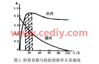
0 Introduction The anti-lock braking system of the car, also known as ABS, is a safety brake control system with the advantages of anti-slip and anti-locking. If there is no ABS system installed, in the event of an emergency, there is no time to step down the brakes, only one foot can be killed. At this time, the wheels are easy to lock, and the vehicle sprints inertia, which may cause side slip, deviation, and direction. Control and other dangerous conditions; while the ABS-equipped car, when the wheel is about to reach the next lock point, the brake can act 60 to 120 times in one second, which is equivalent to constantly braking and relaxing, which is similar to the mechanical " Click brake." Therefore, it is possible to avoid out-of-control and wheel side slip during emergency braking, so that the wheel is not locked when braking, the tire does not rub against the ground at one point, and the friction is increased, so that the braking efficiency reaches 90% or more [1] . This article refers to the address: http:// When the car is braked, the relationship between the adhesion coefficient and the tire slip ratio is shown in Fig. 1, where φ represents the adhesion coefficient. It can be seen from Fig. 1 that when the slip ratio is 15%-20%, the lateral and longitudinal adhesion coefficients are relatively large, and a large number of research experiments also show that the braking effect of the car is the best. The wheel speed signal processing module transforms the input analog wheel speed signal to obtain a regular digital wheel speed input into the processor, and the processor calculates and judges whether each wheel is tending to lock; the solenoid valve driving monitoring module is amplified from The solenoid valve control signal of the processor enables it to drive the actuator (brake pressure regulator) to adjust the brake pressure so that the wheel speed is in a continuously-pressurized boost-pressure-decompression state, while the current solenoid valve control signal is fed back To the processor to monitor the control logic. 2.3 Wheel speed acquisition and processing Electromagnetic wave wheel speed sensor converts wheel speed into sinusoidal signal proportional to wheel speed. Generally, the frequency of wheel speed signal is lower than 1KHz, and the amplitude is relatively low, and the amount of interference is large. It is converted to a square wave signal of TTL level, so a signal conversion circuit is required to input the converted wheel speed signal into the processor. This design adopts 4-channel wheel speed acquisition. The LM324A amplifies the wheel speed signal, and then uses the low-pass filtering and filtering part of the algorithm to reduce the interference amount. Finally, the digital wheel speed signal after 74HC14 shaping is square wave. Can be entered into the processor. When a valid brake signal is detected, the processor collects the wheel speed pulse signal through the wheel speed sensor, and then calculates the vehicle speed and acceleration. When the vehicle speed is high, the slip ratio logic threshold algorithm is called, and the solenoid valve outputs the pressure maintaining, The decompression and supercharging signal, that is, the supercharging at the initial braking, maintains the pressure when the acceleration threshold is reached, and the slip ratio remains in the stable region, and reaches the slip rate stability threshold decompression after a period of time. This reciprocating, the speed of the vehicle is reduced. If the vehicle speed is low, the solenoid valve directly outputs a boost or hold pressure signal. At this time, the wheel speed is always decreasing, and there is no rebound until it is reduced to zero. Figure 6 and Figure 7 show the braking process of a pneumatic brake type heavy-duty vehicle with a low adhesion coefficient road surface and an initial speed of 33 (m/s). Observe the state change of the solenoid valve corresponding to the wheel speed curve: pressurization - holding pressure - decompression; when the wheel speed is rising, the state change of the solenoid valve is: decompression - holding pressure - boosting. It can be seen that the vehicle has better braking effect under the control of the ABS ECU under the control of the ABS ECU, the wheel speed fluctuation is relatively stable, and the braking time is short, so the controller has a good braking effect. Breaker Mcb,Mcb Circuit Breaker,32A Circuit Breaker,Miniature Circuit Breaker ZHEJIANG QIANNA ELECTRIC CO.,LTD , https://www.traner-elec.com
The key control component of the ABS system is the ABS electronic controller, the ECU. Based on the analysis of ABS braking principle and controller structure, this paper selects dsPIC30F5011 single-chip microcomputer with powerful data processing function for a certain type of vehicle, combines ABS system chip, completes ABS_ECU hardware design, and develops control program in self-developed hardware. Simulation experiments were carried out on the loop simulator, and good results were obtained.
1 ABS braking principle In the braking process of a car, the external force that causes the car to brake and decelerate is the ground braking force acting on the tire tread on the tire surface, but the ground braking force depends on the friction of the two friction pairs: It is the friction of the brake device on the wheel, that is, the brake force; the other is the friction between the tire and the road surface, that is, the ground adhesion. Only when the car has sufficient brake braking force and ground adhesion, can it obtain sufficient ground braking force [2]. There is usually a slip phenomenon in the braking process of the automobile, that is, there is a relative slip caused by the speed difference between the vehicle speed and the wheel speed, and the degree of the slip is represented by the slip ratio: 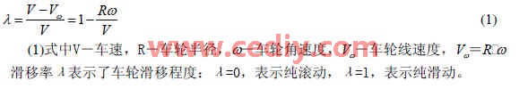
During the braking process of the vehicle, when the wheel tends to lock, the pressure of the brake system is rapidly reduced, the wheel slip rate is restored to the ideal stable zone, and the brake system pressure is adjusted by automatic and high frequency. The wheel slip ratio is kept within a narrow range around the ideal slip ratio to make full use of the longitudinal peak adhesion coefficient between the wheel and the road surface and a high lateral adhesion coefficient, thereby preventing the wheel from locking and obtaining the best braking performance [ 3].
2 ECU hardware design
2.1 ECU structure
The ABS system is mainly composed of a wheel speed sensor, an electronic controller (ECU) and a solenoid valve. The core part of the system is the ECU. Its composition is shown in Figure 2. It mainly includes system power management, wheel speed signal processing, processor (microcontroller), solenoid valve driver and ABS fault detection. 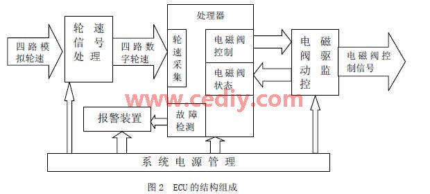
2.2 Processor selection and design
The most critical part of the ECU is the processor. At present, most of the 16-bit MCUs are used as the processor of the ECU. On the one hand, the wheel speed signal is collected into the ABS algorithm, and on the other hand, the solenoid valve control command is sent to the actuator to pressurize the wheel. -Pressure-decompression treatment; at the same time, it also expands the fault detection and solenoid valve monitoring part to ensure the normal operation of the ECU. Whether it is wheel speed acquisition and algorithm processing, or control of wheel brake pressure, there are high requirements for the core processor: strong real-time performance, good stability, and high data processing accuracy. Microchip's dsPIC30F5011 as a high performance 1
The digital signal controller not only has the control function of the single-chip microcomputer, but also combines the processing power of the digital signal of the DSP. The chip contains a complete DSP engine: a high-speed 16×16 integer multiplier, a 40-bit ALU, two 40-bit saturating accumulators, and a 40-bit bidirectional shifter. Improve chip computing power. The instruction system is divided into two categories: microcontroller class and DSP class. The single-stage instruction prefetch mechanism makes most of its instructions single-cycle. On-chip integrated 66K FLASH, 1K EEPROM, 4K RAM, 8-channel input capture, an 8-channel Pulse Width Modulation Module (PWM). Combined with ICD2 (on-chip debugger) in the MAPLAB IDE development environment, program editing, compiling, online debugging and downloading of the microcontroller.
The functional interface distribution of the processor is shown in Figure 3. The dsPIC30F5011's input capture port (IC1...4) is used to collect 4 sets of wheel speed signals. According to the set acquisition mode, the state of the wheel speed signal can be accurately detected. After the ABS algorithm, the 8-channel I/O port output solenoid valve is controlled. The signal, while the solenoid valve status is fed back to the processor by eight I/O ports, forms a closed loop to monitor the algorithm's control logic. At the same time, a PWM port is used to output the alarm light signal, and the fault frequency is determined by setting the blinking frequency of the alarm light. The brake signal from the brake plate is isolated by the optocoupler into the microcontroller. An effective brake signal is an entry condition for entering the ABS algorithm. 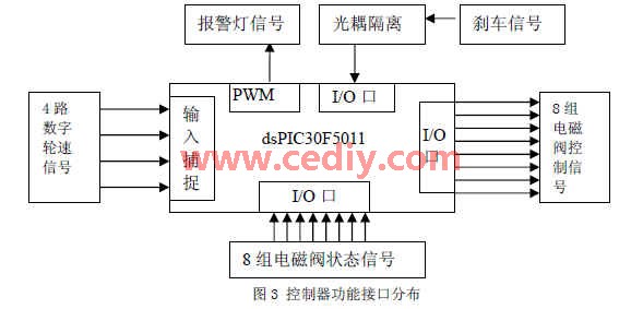
2.4 Output and Processing of Solenoid Control Signal After the ABS algorithm, the processor generates eight solenoid valve control signals to control one wheel in groups of two solenoid valve control signals. The combined control strategy is: 00 holding pressure; 01 boosting; 10 decompression. The solenoid valve control signal output by the processor is only a few tens of milliamps, and the current required by the actuator is 1 to 2 A, so the solenoid valve control signal needs to be amplified. This design uses Infineon's ABS system driver chip TLE6216, each of which can drive four-way solenoid valve control signals, while feeding the current solenoid valve status to the processor to monitor the control effect.
2.5 Power supply and fault detection For the vehicle, the battery or generator is powered. The battery of the heavy-duty vehicle is 24V, the working voltage of the generator is 28V, and the working voltage of the single-chip microcomputer is 5V. Therefore, in addition to the power supply, voltage conversion is required. The design uses Infineon's ABS system power chip TLE6210, which can convert 12V voltage into 5V required by the microcontroller, and integrates alarm light, engine drive and other functions. In addition, the TLE6210 integrates a voltage monitoring logic module. When the input/output voltage is detected to be too high or too low, the RES1/RES2 will generate a reset pulse to reset the entire system. Since the system power supply has an analog part and a digital part, it is necessary to add an isolation inductor between the two parts of the power supply to prevent mutual interference between the analog circuit and the digital circuit in the system.
For the faults generated by ABS, mainly include: system power failure, wheel speed sensor failure, ABS system operation failure, solenoid valve failure, etc., the operator can determine the source and type of the fault by the flashing frequency of the fault alarm light, and the corresponding fault The code is stored in the EEPROM for identification and processing by the host computer.
3 Software Design The current ABS system mainly adopts the method of reference threshold control, namely Bosch control logic. This is a kind of logic that is widely used today. This method combines wheel angular deceleration, angular acceleration and slip ratio as control parameters [4]
In this paper, the control strategy of taking the angular acceleration of the wheel and the angular deceleration as the main threshold and the slip ratio as the auxiliary threshold is adopted. The specific implementation flow chart is shown in Figure 4. 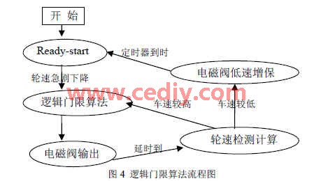
4 Hardware-in-the-loop simulation test uses the hardware-in-the-loop simulation system developed in the previous “863†project “Embedded System Development Platform for Automotive Electronics Control and Its Application†(2004AA1Z2380) (as shown in Figure 5). We simulated the braking process of this ABS controller. The simulation results are shown in Figure 6 and Figure 7. 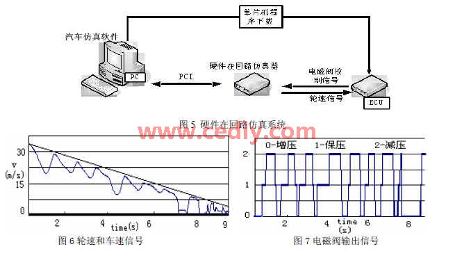
5 Conclusions Microchip's dsPIC30F5011 is used as the processor of the ABS system to achieve rapid acquisition of wheel speed, discrimination processing, and calculation of parameters such as slip rate, ensuring real-time control and stability. At the same time, combined with Infineon's ABS system chip, the power management and solenoid valve drive of the system are optimized. Through many simulation tests, it can be seen that the ABS controller has good braking effect.
The author of this paper innovates: DCS (Digital Signal Controller) dsPIC30F5011 is selected as the processor to solve the fast and large-scale transmission and operation of data. The ABS logic threshold algorithm written in C language can be kept within 5ms; the dedicated ABS is adopted. The chip optimizes the power management and solenoid valve driving of the ABS controller, which can shorten development time and ensure system integrity and stability. Provides test data and design references for the commercialization of ABS controllers.