Characteristic impedance selection in RF systems
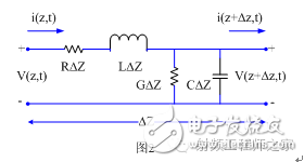
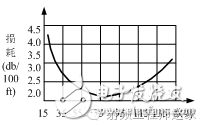
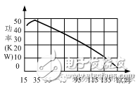
In the RF industry, it is often heard that the characteristic impedance of this cable is 50 ohms, and the characteristic impedance of this microstrip line is 50 ohms and so on. At this time, many beginners or people outside the industry are arrogant: "What?? The "impedance" of the wire is 50 ohms? The quality of this wire is too bad!" "What?? One meter long "impedance" is 50 ohm microwave cable to 500rmb?? Are you teasing me?" ...... Yes, the signal traces in the RF single-disc are mostly microstrip lines with a "characteristic impedance" of 50 ohms; a 50-ohm coaxial cable that can transmit a maximum frequency of 20 GHz is 500 rmb. The reason for these misunderstandings is that we have to distinguish between two physical quantities: one is "impedance" and the other is "characteristic impedance." The latter has more "characteristics" than the former. "Impedance" indicates the magnitude of the conductor's resistance to current flow. The greater the resistance of the conductor, the greater the resistance of the conductor to the current. The unit of resistance is ohms. "Characteristic impedance" is the inherent characteristic of the RF transmission line that affects the amplitude and phase change of the high-frequency wave voltage and current. It is equal to the ratio of voltage to current everywhere. The unit of characteristic impedance is also ohm. To understand the concept of "characteristic impedance", we must first figure out what a transmission line is. Simply put, a transmission line is a connection that can transmit signals. Power lines, video lines, USB cables, and traces on the PCB can be called transmission lines. If the signal transmitted on the transmission line is a low frequency signal, assuming 1KHz, then the wavelength of the signal is 300 kilometers (assuming the signal speed is the speed of light), even if the length of the transmission line is 1 meter long, it is still very short relative to the signal. The amplitude and phase effects of the signal are small. However, for high-speed signals, assuming that the signal frequency is increased to 300 MHz, the signal wavelength is reduced to 1 meter. At this time, the transmission line of 1 meter and the wavelength of the signal are completely comparable, and there is a wave effect on the transmission line. The voltage and current at different points will be different. In this case, we can't ignore the impact of the transmission line on the signal. The transmission line is a line relative to the signal, we have to use the theory of long-line transmission to solve the problem. On the premise that the transmission line is a long line, the model of the transmission line is no longer a wire model with a low impedance, but a distributed parameter network. As shown in Fig. 1, the transmission line is often indicated by a double line. The length of the infinitesimal length Δz in Fig. 1 can be simulated as a lumped element circuit in Fig. 2, where R, L, G, C are the unit length. , defined as follows: R represents the series resistance per unit length in Ω/M During the transmission of the signal in the transmission line, an electric field is formed between the transmission line and the reference plane at a point where the signal arrives, and a current and a voltage are generated. The ratio of the voltage to the current is the characteristic impedance Z of the wire. R and G represent loss, L and C are storage devices. The transmission line models we generally study are low loss or lossless transmission lines. The characteristic impedance of the transmission line can be written as Therefore, the characteristic impedance reflects the influence of the distribution parameters L and C of the transmission line on the amplitude and phase of the high frequency signal. Why are characteristic impedance selections in RF systems all 50 ohms? Instead of 10 ohms, 100 ohms? There are actually two standards in the RF system, one is a 75 ohm system and the other is a 50 ohm system. The radio and television system is a 75 ohm system, and its corresponding transmission line is a 75 ohm transmission line; in other radio systems, it is basically a 50 ohm system, and its corresponding transmission line is a 50 ohm transmission line. The characteristics of the transmission line determine the standard impedance of the two systems. Studies have shown that the loss per unit length of the coaxial cable and the power that can be transmitted are related to the impedance characteristics of the cable. It can be seen from FIG. 3 and FIG. 4 that the transmission loss of the coaxial cable characteristic group impedance is the lowest at 77 ohms; the coaxial cable characteristic group impedance has the maximum carrying power at 30 ohms. The early radio and television system was a one-way transmission network, and the characteristic impedance with a small loss was selected to be 75 ohms. Other radio communication systems are mostly two-way networks. It is necessary to consider the loss to be small, and also to take into account the large power that can be withstood during transmission. The overall choice of 50 ohms is the best solution! Figure 3. Coaxial cable loss and characteristic impedance relationship Figure 4. Coaxial cable bearing power and characteristic impedance relationship KNLE1-63 Residual Current Circuit Breaker With Over Load Protection
KNLE1-63 TWO FUNCTION : MCB AND RCCB FUNCTIONS
leakage breaker is suitable for the leakage protection of the line of AC 50/60Hz, rated voltage single phase 240V, rated current up to 63A. When there is human electricity shock or if the leakage current of the line exceeds the prescribed value, it will automatically cut off the power within 0.1s to protect human safety and prevent the accident due to the current leakage.
KNLE1-63 Residual Current Circuit Breaker,Residual Current Circuit Breaker with Over Load Protection 1p,Residual Current Circuit Breaker with Over Load Protection 2p Wenzhou Korlen Electric Appliances Co., Ltd. , https://www.zjmannualmotorstarter.com
L represents the series inductance per unit length in H/M
G represents the parallel conductance per unit length in S/M
C represents the parallel capacitance per unit length in F/M 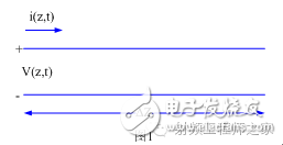
leakage breaker can protect against overload and short-circuit. It can be used to protect the line from being overloaded and short-circuited as wellas infrequent changeover of the line in normal situation. It complies with standard of IEC/EN61009-1 and GB16917.1.