Principle analysis of three-phase phase loss detection circuit
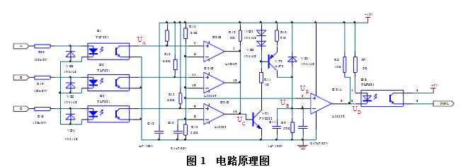
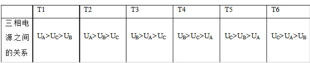
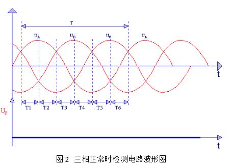
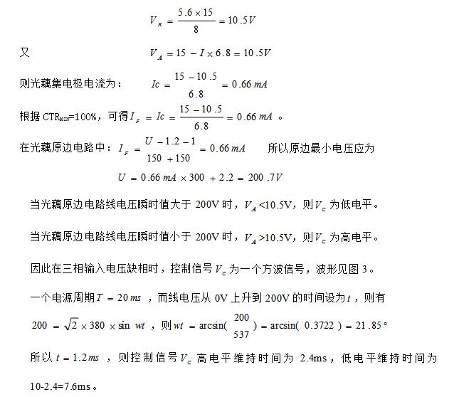
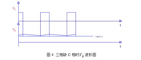
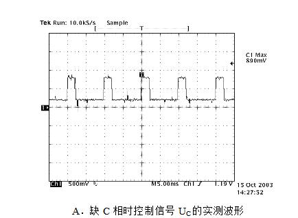
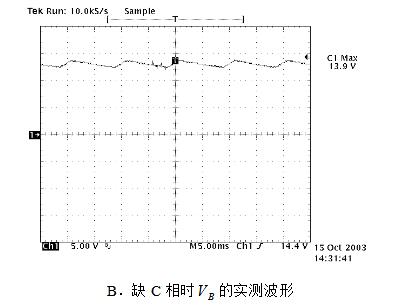
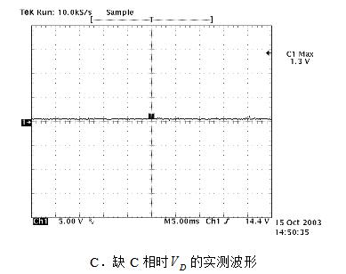
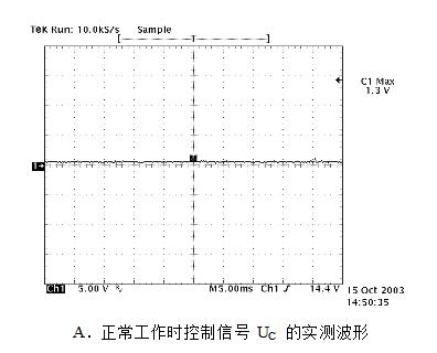
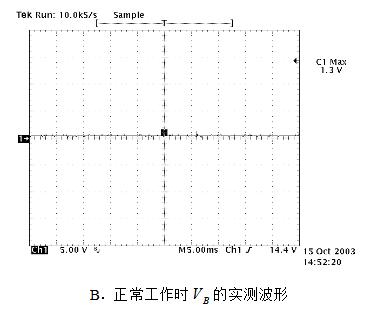
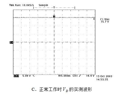
For the electrical equipment using three-phase alternating current, one of the most basic reliability protection functions is the three-phase input phase loss detection function. When any phase of the three-phase input is out of phase, the circuit module outputs a phase loss alarm signal. Through the processing of the alarm signal, the safety protection of the electrical equipment is ensured. 1, circuit schematic The schematic is shown in Figure 1: 2, the working principle Its working principle is as follows: When the three-phase input voltage is normal, the three-phase input phase voltage waveform is shown in Figure 2. For analysis, a power cycle is divided into six equal parts, as shown in Figure 2, T1, T2, T3, T4, T5, T6. In these six intervals, the relationship between the three-phase power supplies is shown in Table 1: In the interval T1, UA "UC" UB, the phase A voltage is the largest, and the phase B voltage is the smallest, therefore, in Fig. 1 The aperture D1 and the diode VD5 are turned on. At this time, the control signal UC is at a low level. When the time enters the T2 interval from T1, the UA "UB" UC, the phase A voltage is the largest, and the phase C voltage is the smallest. Therefore, in Fig. 1 middle The aperture D1 and the diode VD4 are turned on, the control signal UC is at a low level, and so on, in the interval T3, T4, T5, T6, the control signal UC is at a low level, so, in one power supply cycle, the control signal UC is low, that is, when the three-phase input voltage is normal (no phase loss), the control signal UC is always low, so that the phase loss alarm signal PHFL is low, indicating that the input is normal. When the three-phase input voltage is out of phase, the waveform of the detection circuit is shown in Figure 3. Due to the lack of phase C, the line voltage is only one phase of UAB. When UAB is near the zero crossing point, the aperture D1 is not conducting. The other two apertures are not turned on. At this time, the control signal UC is at a high level, so that the phase loss alarm signal PHFL is at a high level, indicating that the input phase is missing and sent to the ECU for processing. 3, circuit design instructions (1) Calculation of control signal CV In Figure 1, the voltage at each point is described as follows: VA: optical output; VB: voltage comparator LM339 pin 4 input; VC: triode VT1 base control signal; VR: comparison comparator voltage reference for all comparators. The current transmission ratio of the aperture TLP621GR takes the minimum value, that is, CTRMIN=100%. The voltage reference VR is: (2) Analysis and calculation of charge and discharge circuits The charge and discharge circuit is composed of resistors R9, R10, VT2, C10, and C11. When the control signal CV is high, the transistors VT1 and VT2 are turned on, and the +15V power supply is supplied to the capacitors C10 and C11 through the resistors R9 and R10. When the control signal CV is low, the transistors VT1 and VT2 are turned off, and the capacitors C10 and C11 are passed. Resistor R9 discharges. Obviously, BV actually adds a ripple signal to a DC voltage. As long as the BV wave is not less than 10.5V, the output of the second pin of the voltage comparator LM339 is always low, and the phase loss alarm signal PHFL. A high level indicates that the three-phase input is out of phase. The waveform is shown in Figure 4. This experiment was carried out on the ZXD5000 100A (V2.0) switching rectifier. The test waveforms for phase loss and normal operation are shown in Figure 5 and Figure 6: Fig. 5 The measured waveform of the detection circuit when the three phases lack the C phase Figure 6 Measured waveform of the detection circuit during normal operation The circuit realizes the three-phase AC input voltage phase loss detection function. When any one of the three phase inputs is out of phase, the circuit module outputs a phase loss alarm signal. The test results are consistent with the theoretical analysis. Solar Home Lighting System Kit SHENZHEN CHONDEKUAI TECHNOLOGY CO.LTD , https://www.szsiheyi.com