CNC machine tool without alarm failure repair - Database & Sql Blog Articles
The control system of the CNC machine tool has a fault self-diagnosis function. Generally, alarm information appears when a fault occurs. According to the fault handling method in the manual, most faults can find a solution. However, there are some faults with no alarms, the phenomenon is not very obvious, and there is a lack of information needed for maintenance. If you pay attention to it after a fault, it will cause the workpiece to be scrapped in batches. Since there is no hardware or software alarm display when the fault occurs, the analysis and diagnosis is difficult. For example, after the machine is powered on, the crawling phenomenon occurs when the X axis is operated manually or automatically, without any alarm display; the machine stops suddenly when the machine is running automatically, and there is no alarm display on the CRT display; an abnormality occurs when running a certain axis of the machine Sound, generally no fault alarm display. Coded pin connection table Further inspection revealed that the C8 output driver integrated circuit inside the encoder had been damaged. After replacing the integrated circuit, reinstall the encoder and adjust the rotor angle to return the machine to normal.
ZGAR bar 4000 Puffs
ZGAR electronic cigarette uses high-tech R&D, food grade disposable pod device and high-quality raw material. All package designs are Original IP. Our designer team is from Hong Kong. We have very high requirements for product quality, flavors taste and packaging design. The E-liquid is imported, materials are food grade, and assembly plant is medical-grade dust-free workshops.
Our products include disposable e-cigarettes, rechargeable e-cigarettes, rechargreable disposable vape pen, and various of flavors of cigarette cartridges. From 600puffs to 5000puffs, ZGAR bar Disposable offer high-tech R&D, E-cigarette improves battery capacity, We offer various of flavors and support customization. And printing designs can be customized. We have our own professional team and competitive quotations for any OEM or ODM works.
We supply OEM rechargeable disposable vape pen,OEM disposable electronic cigarette,ODM disposable vape pen,ODM disposable electronic cigarette,OEM/ODM vape pen e-cigarette,OEM/ODM atomizer device.
ZGAR bar 4000 Puffs Disposable Vape, bar 4000puffs,ZGAR bar 4000 Puffs disposable,ZGAR bar 4000 Puffs,ZGAR bar 4000 Puffs OEM/ODM disposable vape pen atomizer Device E-cig ZGAR INTERNATIONAL(HK)CO., LIMITED , https://www.szvape-pods.com
For the failure display failure, it is necessary to analyze and judge according to the change status before and after the failure occurs. For example, the X-axis crawls during operation, and it can be judged whether it is a CNC partial fault or a servo partial fault. The specific method is: in the manual pulse feed mode, the manual pulse generator can be uniformly rotated, and the rate of change of the Y, Z and X three-axis feed numbers on the CRT display is separately observed. Usually, if the CNC part is normal, the rate of change of the three axes should be basically the same, so that it can be determined whether the crawling fault is caused by the servo portion of the X-axis or the mechanical transmission. The following are some troubleshooting methods for encountering no alarms during maintenance.
Example 1. A horizontal machining center with a SIEMENS 810MGA3, the X, Y, and Z axes can be slowly moved to the specified direction after the manual direction keys are pressed. However, the movement speed and coordinate position are incorrect. Call the police.
Such failures are usually caused by poor machine position detection systems. On this machine, through the system following the error page check, it is found that the position following error also changes during the movement of the machine tool, but the speed of change is very slow, which is inconsistent with the actual moving distance of each axis. Based on experience, check from the software side.
First check the parameter settings of the system's position control system. In the SIEMENS810/820MGA3 system, the main parameters related to the position control system are:
MD5002bit2, 1, 0: Control resolution of the position control system.
MD5002bit7, 6, 5: Input resolution of the position control system.
MD3640, 3641, 3642: The number of feedback pulses per revolution of the X, Y, and Z axes (the value after 4 times the frequency).
MD3680, 3681, 3682: Number of command pulses per revolution of the X, Y, and Z axes (in units of resolution of the position control system).
On this machine, the X, Y and Z axis servo motors are equipped with 2500 pulse encoders. The position control system has a control resolution of 0.5 μm, the position control system has a command resolution of 1 μm, and the X, Y and Z axis screw pitches. For 10mm, the lead screw is directly connected to the motor. Therefore, the correct parameter settings should be:
MD5002bit2, 1, 0=100;
MD5002bit7, 6, 5=010;
MD3640, 3641, 3642 = 10000;
MD3680, 3681, 682=200000
Check the system parameter settings and find that the MD3680, 3681, 3682 in the system is set to 1, which does not match the actual machine tool; after changing the parameters, the machine tool returns to normal.
Example 2. A gantry machining center using SIEMENS 810M is equipped with a 611A spindle drive. When the spindle positioning command is executed, it is found that the spindle has obvious position overshoot, the positioning position is correct, and the system has no alarm.
Since the system has no alarm, the spindle positioning action is correct, and it can be confirmed that the fault is caused by poor adjustment of the spindle drive or system.
There are many ways to solve the overshoot, such as reducing the acceleration and deceleration time, increasing the speed loop proportional gain, reducing the speed loop integration time, and so on. Check the spindle drive parameters of this machine and find that the acceleration/deceleration time of the drive is set to 2s. This value is obviously too large. After changing the parameters and setting the acceleration/deceleration time to 0.5s, the position overshoot is eliminated.
Example 3. A Zhongjie THY5640 vertical machining center finds abnormal noise in the spindle and gearbox when the spindle speed is <500r/min. Observing the power meter of the motor, the output power of the motor is unstable. However, the abnormal sound disappears when the spindle speed is >1201r/min. After starting up, in the absence of a rotation command, the power meter of the motor will swing on its own, and the motor will drift by itself. The braking time is too long after normal operation, and the machine has no alarm.
As a rule of thumb, the cause of this failure may be due to loss of control of the spindle controller, mechanical transmission or motor. Due to the large amount of work involved in the disassembly of the mechanical part, the spindle controller of the electric part is checked first, and the controller is Siemens 6SC-6502. First check the preset parameters in the controller, and then check the control board, there is no abnormality. After viewing the board is dirty, the board is cleaned as required, but the boot fault is still the same after installation. Therefore, the controller failure can be eliminated. In order to determine whether the fault is in the motor or in the mechanical transmission part, the motor and the machine must be disengaged. After the vehicle is turned off, the test will start to give an uninterrupted abnormal sound when the motor speed command is close to 450r/min, but the abnormal sound is given when the command is 1201r/min. disappear. After analysis, it is considered that when the low speed given 450r/min command and the high speed 4500r/min command, the motor is at the highest speed, but the gear is decelerated at low speed, so the fault can be basically determined in the motor part. After analysis, the abnormal sound may be caused by poor bearing. The motor was disassembled and inspected, and it was found that the bearing was indeed broken. At high speed, the bearing was stuck, causing the load to increase, causing the power meter to oscillate and deflect. After the motor has no rotation command, the motor drifts too slowly after the normal operation. After checking, the disc of the encoder is cut, and all the faults are eliminated after replacing the bearing and the encoder.
This fault is mainly caused by abnormal sound when the spindle rotates. Therefore, the sound source should be checked and then checked. Abnormal sounds are commonly caused by mechanical rubbing, jamming and bearing damage.
Example 4. A CNC lathe with FANUC 0T numerical control system, after starting up, as long as the Z axis moves, it will violently oscillate. The CNC has no alarm and the machine can't work normally.
After investigation, it was found that the Z axis of the machine tool works normally when moving <2.5mm, and the movement is smooth and vibration-free; once the above range is exceeded, the machine tool will vibrate violently. After analysis, the position control part of the system and the servo drive itself should be fault-free, and the fault is initially determined on the position detecting device, ie the pulse encoder.
Since the machine tool has a semi-closed loop structure, the motor is replaced during maintenance, and the cause of the fault is determined to be caused by a defective pulse encoder.
In order to understand the root cause of the fault, the following analysis and test were made: (1) In the case of the main circuit of the servo drive being powered off, the motor shaft was manually turned, the system display was checked, and the system display was found regardless of the forward and reverse rotation of the motor. The actual position value can be correctly displayed on the top, indicating that the A, B, *A, and *B signals of the position encoder are output correctly.
(2) Since the machine tool Z-axis screw pitch is 5mm, vibration occurs as long as the Z-axis moves about 2mm. Therefore, the cause of the fault may be related to the actual position of the motor rotor, that is, the rotor position detection signals C1, C2, C4 of the pulse encoder. And C8 is bad.
According to the above analysis, it is considered that the Z axis can move normally by about 2.5 mm, which is equivalent to the actual rotation of the motor by 180°. Therefore, the portion where the failure is further determined is that the C8 in the rotor position detection signal is defective.
After removing the pulse encoder, according to the connection requirements of the encoder, after adding DC 5V to the pins N/T and J/K (as shown in the table below), rotate the encoder shaft and measure Cl, C2, C4 with a multimeter. At C8, it was found that there was no change in the state of C8, and it was confirmed that the rotor position detection signal C8 of the encoder was defective. 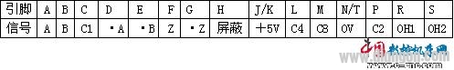
In different numerical control equipment, the performance of no alarm failure is different. For example, when a CNC lathe appears in the diameter direction, it is more likely to be small. There are many errors in the vertical axis on the machining center. It is common for the size to gradually increase downward, but there is also a phenomenon in which the size increases upward. On the horizontal axis, there are often some small error faults, some often Changes, good times and bad times make the size of the parts difficult to control. In addition, the following conditions will cause the CNC system to have no alarm failure.
(1) The numerical control system is relatively simple, no detection is set for the error, or the detection system has been set, but the error occurred in the machine tool is not within the predicted range of the design, and is not detected when an error occurs. If you are using a semi-closed loop system, you cannot detect the actual position of the machine.
(2) The zero return mode of the electrical system of the machine tool is improperly set, and the zero return point cannot be guaranteed to be consistent. In this case, the error is generally small. In addition to the failure caused by the deceleration switch, the deceleration distance when returning to zero will also cause the zero point to deviate. In some systems, there is a “delete amount†in the monitoring page, which is recorded and frequently checked to find problems in time.
(3) The structure of the screw and the motor coupling is different. The phenomenon is different after the failure. Some sizes only increase in the negative direction, and some positive and negative changes may occur. According to experience, the coupling is elastically coupled. Basically, the negative direction increases, while the key connection occurs both faults.
Example 5. For a BX-110P machining center equipped with FANUC 11 system, when the JOG mode is used, the robot can not reduce the claw when picking up the tool, but it does not alarm; the mode is selected to the ATC state, and the manual operation is normal.
After viewing the ladder diagram, the limit switch LS916 is not pressed. After adjusting the position of the limit switch, the machine returns to normal. However, after a while, the fault occurred again, and the LS916 was not loosened, but it was not pressed, and it was suspected that the manipulator's hydraulic cylinder rod did not reach into position. After checking, it was found that the set screw of the lock nut of the top end of the hydraulic cylinder rod was loose, and the stroke of the expansion and contraction of the hydraulic cylinder was changed. Troubleshoot after adjusting the lock nut and tightening the set screw.
