Development and function of bypass capacitor
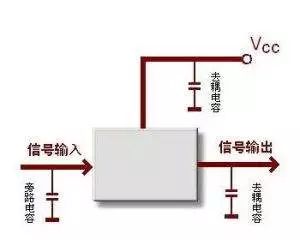
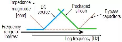
The bypass capacitor design is a relatively common design, but how should the bypass capacitor be designed and how many bypass capacitors are designed? The development of the times is always reinventing. Just like "The Romance of the Three Kingdoms" said that the general trend of the world is to divide together for a long time and divide for a long time. Figure 1. A computer board from the 1960s and 1970s using diodes and transistors This is an old computer board full of diodes and transistors that performs a simple DTL gate function (diode crystal logic). It was produced approximately in the 1960s or early 1970s. In our distribution design course, I used this computer board to ask a question: Can you count how many bypass capacitors are on this board? The answer is surprisingly zero. Why is it that today we are looking everywhere on the circuit board to place a lot of bypass capacitors to reduce the noise of our electronic products? Now whether it is a new laptop or a large computer board, we can find hundreds or even thousands of capacitors on it. In order to understand the cause of this significant change in just a few decades, we must study the role of bypass capacitors and how the bypass capacitors work. Whether it is analog or digital, all electronic circuits will eventually generate (and / or) program interactive electrical signals. During their operation, the supply current they draw from the power source is constantly changing, and it is necessary to determine the required supply current according to the actual operation. Sometimes the circuit needs less current, sometimes it is a lot, and the changes in different needs in this also constantly change the current in the power rail. These constantly changing currents flow through the wires and the wiring and layers between the power supply and electronic devices on the printed circuit board, producing voltage changes: ∆V is the voltage change, L represents the inductance in the supply path; dI / dt changes the rate of current change with time. Small voltage fluctuations will be accepted by electronic devices, but each circuit will have a maximum and minimum limit to ensure normal operation. We must try to limit the change of the power supply voltage, otherwise it will change because of the change of the required current. We must place the accumulator between the series inductance in the circuit and the power path. The capacitor is a good accumulator, because unlike an inductor, the voltage across the capacitor (if we ignore its parasitic elements) will not change drastically due to sudden current changes. To determine what we are and how many capacitors, it is more convenient to look at the problem from the point of entry in the frequency domain. The power distribution network (PDN) can be simulated in many different forms, from simple lumped equivalent circuits to detailed grid models. For what we are discussing now, I think a simple lumped equivalent circuit is enough. The graph in Figure 2 shows the simplified PDN equivalent impedance. To create a familiar Bode plot diagram, we use the log indicator log-log on the coordinate axis. Please note that for the sake of simplicity, this chart only shows the impedance value, but in future articles we will realize that it is very important at this stage when we use PDN impedance to calculate the performance of the circuit. Figure 2. Simplified PDN lumped equivalent impedance The blue line on the way represents the impedance of the power supply, which can be a battery or a power converter. At low frequencies, the impedance is lower, but at higher frequencies, the inductance of the wires, wiring, and connection layers will eventually dominate. The green line represents the impedance of the active device. If we correspond to the impedance icon at the board package interface, the green line represents the impedance of the active device together with the package and the PDN capacitor on the package. We call those active devices "silicon silicon", but they can be any type of active circuit: the active device on that old computer board is a germanium transistor. In summary, the blue and green lines produce a triangular impedance configuration, and the tails at low and high frequencies are flat. If no bypass capacitor is added to this system, any noise current may cause a lot of noise every time it hits this triangular peak frequency. The thick black line extending from left to right on the frequency axis is used to indicate the frequency range we are interested in and is related to the PDN impedance. The frequency range we are interested in is not necessarily part of a continuous spectrum, especially for composite circuits that have different functions connected to the same power supply voltage. If the frequency range to be studied is not between the frequency of the impedance peak formed by the blue and green curves, then the circuit will work normally without adding bypass capacitors. If the operation of the circuit excites the impedance peak, then we need to increase the bypass capacitor to reduce the impedance and thus reduce the noise. The red dotted line on the icon represents the impedance of a bypass capacitor, which is used to supplement the impedance of the power supply and active devices, and also makes the overall impedance value of the wide frequency band lower. So why don't you need bypass capacitors on old computer boards? The main reason is that the switching of the germanium transistor is slow, and the clock frequency is very low, that is, the short switching current does not excite the high impedance part of the PDN impedance. Today's high-speed electronic products, complex circuit functions and high clock frequency, most of the time we have to care about a wide bandwidth PDN impedance, therefore, we can not allow a very high impedance between the source and load impedance Peak. Therefore, we need bypass capacitors. If we fast forward for decades, we can easily predict that the circuit board will no longer have bypass capacitors. Because, when the distributed power supplies are small enough that we can place them very close to the load, the interconnection inductance will become lower, and the chip and package capacitance in the active device will be larger, so we will It's back to the era when no bypass capacitors were needed on the circuit board. We've been around for over 16+ years. We make sure our sound is The Best Sound. Customized Headphones, personalized gifts, promotional products custom , Bluetooth Earphones,Best Headphones TOPNOTCH INTERNATIONAL GROUP LIMITED , https://www.mic11.com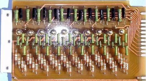

Our products include gaming headset, Bluetooth Earphone, Headphones Noise Cancelling, Best Wireless Earbuds, Bluetooth Mask, Headphones For Sleeping, Headphones in Headband, Bluetooth Beanie Hat, bluetooth for motorcycle helmet, etc
Manufacturing high-quality products for customers according to international standards, such as CE ROHS FCC REACH UL SGS BQB etc.
We help 200+ customers create custom Bluetooth headphones, earbuds, earphones, etc audio products design for various industries.