A design for burning firmware generated by source program compilation to target chip
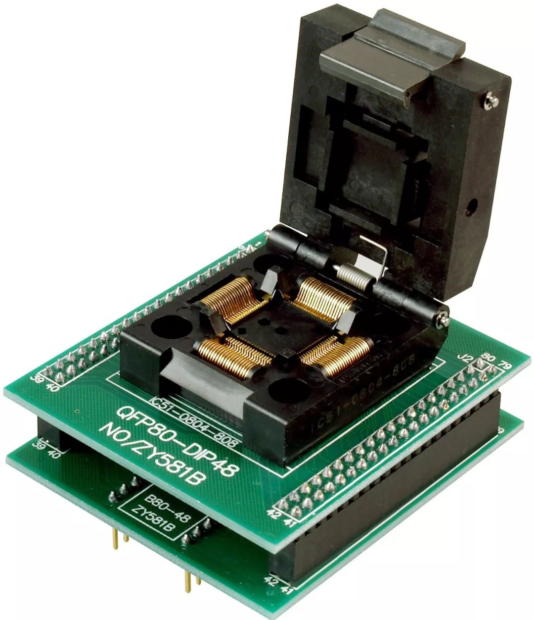
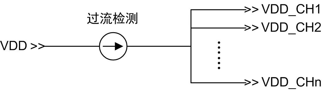
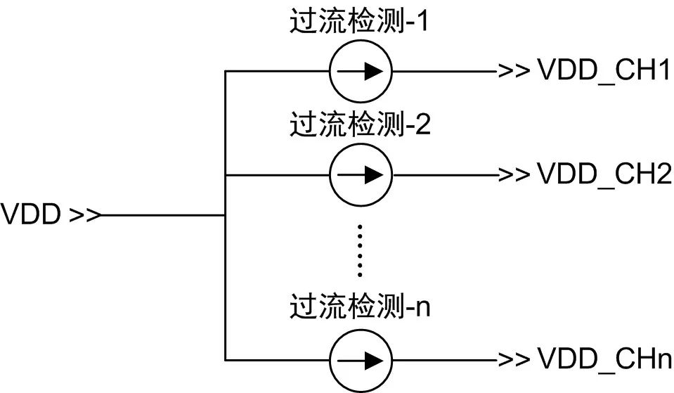
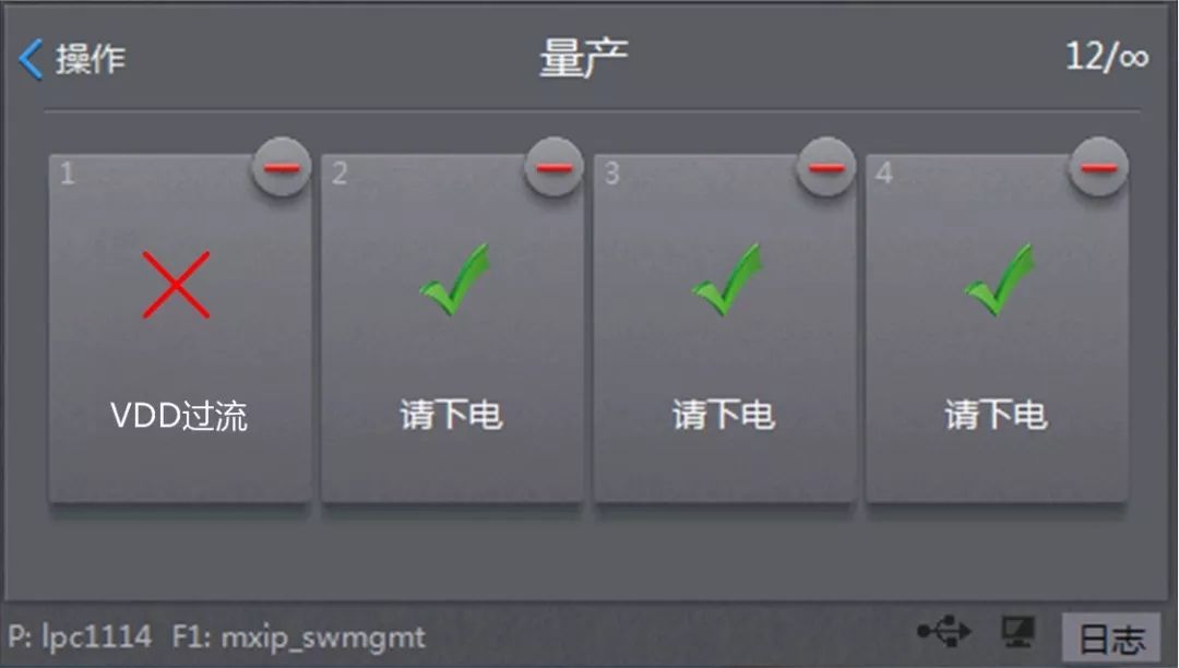
Introduction to this article Programmer, also known as burner and code writer, is a device that burns the firmware generated by the source program to the target chip. According to the programming method, it can be divided into on-board programming and bare die programming. On-board programming: also known as ICP programming, which is to solder the chip to the PCB and then program. Bare chip programming: also known as offline programming, it is to put the chip on the fixture for programming, and then solder the chip to the PCB. Possible over-current situation 1. Write on the board In the process of plugging and unplugging the download line, short circuit and overcurrent caused by connecting the wrong line; The PCB board has a welding short circuit problem during the production process, and the overcurrent phenomenon will occur when the programmer is powered on; There is a large-capacity capacitor on the PCB board, and the inrush current is too large when the programmer powers on the PCB board, thereby triggering the overcurrent protection mechanism by mistake. 2. Bare chip programming When the chip is placed in the programming socket, the chip is biased or the chip pins are skewed, causing a short circuit and overcurrent when the programmer is powered on; Remove the chip from the board. If there is any tin residue on the chip pins, it is put on the programming socket for programming, which causes the programmer to be electrically short-circuited. If the power supply over-current protection of the programmer is not perfect, when encountering a short circuit of the chip or circuit board, the programmer may be damaged at least, and the chip or circuit board may be damaged, causing serious production accidents. The multi-channel mass production programmers on the market usually only have one overcurrent detection and protection circuit. After detecting the overcurrent of the power supply, the total power output is directly turned off. Single channel overcurrent detection This design can protect to a certain extent, but it also has obvious defects: When an overcurrent occurs in one of the channels, the overcurrent protection is triggered and the power output is turned off, causing other normal channels to fail to burn; The over-current threshold is set very high. When there is only one channel short-circuited, the short-circuit current may not reach the over-current threshold and cannot trigger over-current protection, causing the corresponding power control circuit of the channel to be burned; When the board is programmed, if there is a large-capacity capacitor on the board, the inrush current is too large at the moment of power-on, and the overcurrent protection may be triggered by mistake to turn off the power supply, resulting in programming failure. In order to completely solve these problems, combined with ZLG Zhiyuan Electronics' more than ten years of programmer development experience, and collecting feedback from customers in various industries, we have rebuilt the overcurrent detection protection of the programmer in the latest P800 series programmer. Mechanism, the core design is to have overcurrent detection protection in each programming channel. Multi-channel overcurrent detection Through new hardware design and software optimization, the overcurrent detection protection of P800 series programmers perfectly solves the problems of traditional programmers. Accurately identify short-circuit and over-current channels, and turn off the corresponding channel power output without affecting other normal working channels. The over-current threshold of each channel can be set, the over-current detection sensitivity is greatly improved, and the programmer and the chip to be burned are effectively protected. Intelligently identify whether it is an overcurrent caused by a short circuit or an instantaneous overcurrent caused by an excessive surge current at power-on. If the overcurrent is caused by the latter, P800 will continue to output power and reduce the instantaneous inrush current through soft start to ensure stable and reliable power-on.
WARNING!
Do not plug two or more meters together!
IMPORTANT
Don't plug in an appliance where the load
exceeds 16 Amp. Always ensure the plug of any appliance is fully
inserted into the meter outlet. If cleaning of the meter is required,
remove from mains power and wipe meter with a dry cloth.
KEYBOARD DEFINITION
1). SET: Set price with button UP.
2). MODE: Exchange display state.
3). UP: Set price combined with button SET.
GENERAL FEATURES
1).Display line power.
2).Display and memory accumulative total power quantity.
3).Display and memory total power charge of price.
THE DATA DISPLAY
Press MODE button the data displays as follows:
W →KWh →PRICE →COST/KWH
↑_ _ _ _ _ _ _ _ _ _ _ _ _ _ _ _↓
1). Plug in socket and power on, the meter will display real power.
2). Press MODE button once again and release, the meter will display accumulative KWh.
3). Press MODE button once again and release, the meter will display total power charge.
4). Press MODE button once again and release, the meter will display COST/KWH.
SETTING PRICE OF COST/KWH
1). Press SET button during display COST/KWH,the first digital COST/KWH flash, press UP button to set it.
2). Press SET button once again and release, the second digital COST/KWH flash, press UP button to set it.
3). Press SET button once again and release, the third COST/KWH flash, press UP button to set it.
4). Press SET button once again and release, the fourth COST/KWH flash, press UP button to set it.
5). Press SET button once again and release, the radix point COST/KWH flash, press UP button to set it.
DATA CLEAR
Press and hold MODE button for 5 seconds will clear KWH,PRICE and COST/KWH data.
Power Backlit, Backlit socket, power meter Backlit, energy meter Backlit, backlit adaptor, backlit plug socket NINGBO COWELL ELECTRONICS & TECHNOLOGY CO., LTD , https://www.cowellsocket.com