Design and analysis of WLAN three-band antenna used in mobile phones
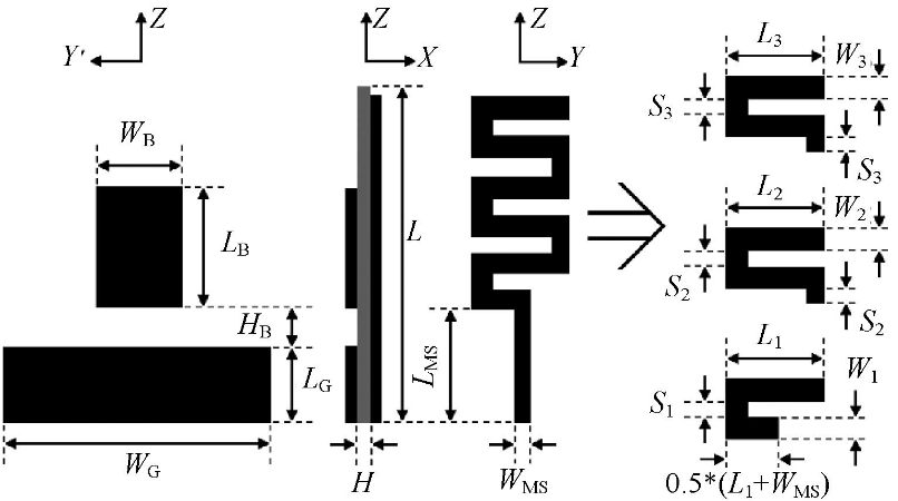
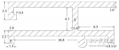
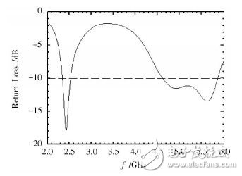
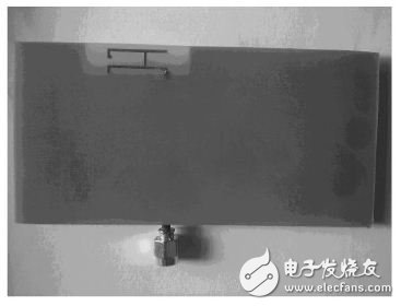
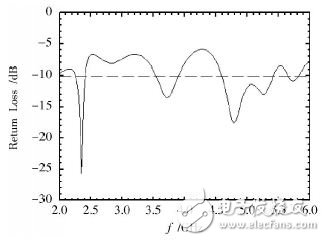
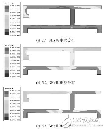
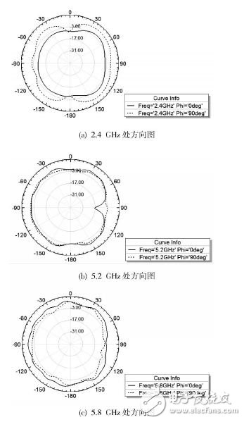
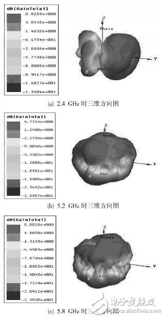
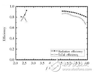
A wireless local area network (WLAN) based on the IEEE 802.11 standard allows wireless connection in a 2.4 GHz or 5 GHz radio frequency band in an ISM (IndustrialScienTIfic and Medical) band that does not require authorization in a local area network environment. Therefore, WLAN, as one of the most effective wireless access networks, has been widely used in wireless communications. Compared with the use of twisted pair copper wire to form a local area network, WLAN has the advantages of being movable, faster, lower cost, and more reliable. With the WLAN IEEE 802.11a standard (5.15~5.35 GHz, 5.725~5.825 GHz) and the IEEE 802.11b/g standard (2.4~2.483 5 GHz), WLAN has developed rapidly. At the same time, it is required that the band performance can simultaneously reach the IEEE802.11a/b/g standard. With the rapid development of wireless communication, handheld mobile terminal devices have become a necessity for people's daily lives. As the most common type of mobile phone, mobile phones are being asked for higher and higher requirements. Light, thin and small have become the trend of mobile phone development. That is, an antenna that meets the requirements is designed in a very limited space, which makes the design of the antenna more difficult. Microstrip antennas are widely used in mobile phones due to their small size, low profile, light weight, easy processing, and low cost. A series of improvements have been made based on the characteristics of the microstrip antenna. This includes the use of coplanar waveguide feed, multilayer structure, and gap loading techniques to achieve bandwidth increase and antenna size reduction. This paper designs a microstrip antenna with a length of 19 mm and a width of 7.5 mm. It is small in size, simple in structure and easy to process. It can work in the 2.4 GHz, 5.2 GHz, and 5.8 GHz bands of wireless LANs. High application value. The mobile phone board is simulated with a common FR4 substrate measuring 118 mm & TImes; 58 mm, thickness 1.2 mm, and a relative dielectric constant of 4.4. The antenna occupies a PCB area of ​​7.5 mm & TImes; 19 mm, and the back is cut to a floor size of 9 mm & TImes; 33 mm. The specific dimensions of the WLAN antenna structure are noted in Figure 2. In Figure 2, A is the feed point and B is the ground point, and its width is 1.1 mm. Figure 1 Schematic diagram of WLAN antenna structure Figure 2 WLAN antenna specific structure and size (unit: mm) The structure shown in Figure 2 was simulated with simulation software. The sweep range was set from 2 to 6 GHz. The impedance bandwidth of -10 dB was obtained as shown in Figure 3. It can be seen from Figure 3 that the bandwidth is -10 dB, the bandwidth of the low-frequency part is 2.344~2.528 GHz, and the bandwidth of the high-frequency part is 4.607~5.859 GHz, which completely covers the IEEE 802.11a/b/g standard. Figure 3 antenna S11 simulation results On this basis, an antenna is made, and the photo is shown in Figure 4. Figure 4 Physical map of the WLAN antenna The S-parameters of the antennas were tested using an Agilent E5071C vector network analyzer. Fig. 5 is a measured result of the parameters of the antenna S11. As can be seen from Figure 5, the measured results reach the three-band bandwidth requirements of the WLAN. Figure 5 S11 measured results of the WLAN antenna Figure 6 Simulation results of return loss for different S lengths Change the length of S in the antenna shown in Figure 2 and perform simulation comparison. The result is shown in Figure 6. As can be seen from Figure 6, the length of S has a large impact on the bandwidth of the high frequency portion of the WLAN antenna. Figure 7 shows the current distribution of the designed antenna at the three frequency points of 2.4 GHz, 5.2 GHz, and 5.8 GHz. It can be seen from Fig. 7 that the current at 2.4 GHz is mainly concentrated in the upper left part and the lower branch line, and the current at 5.2 GHz is mainly concentrated in the lower branch circuit, and the current at 5.8 GHz is mainly concentrated in the upper right part and the lower branch line. Figure 7 Current distribution of the antenna at different frequencies Figure 8 Two-dimensional pattern at different frequencies Figure 8 shows the two-dimensional pattern of the antenna at 2.4 GHz, 5.2 GHz, and 5.8 GHz. It can be seen from Figure 8 that the pattern is omnidirectional at all three frequencies. At high frequencies, the slight change in the size of the antenna will result in a large change in the surface current distribution, so the pattern has a certain tortuosity. Figure 9 shows the three-dimensional pattern of the antenna's gain at 2.4 GHz, 5.2 GHz, and 5.8 GHz. The gain is 5.37 dB at 2.4 GHz, 2.4 dB at 5.2 GHz, and 4.77 dB at 5.8 GHz. Figure 9 Three-dimensional pattern at different frequencies Figure 10 Antenna efficiency Figure 10 shows the radiation efficiency and total efficiency of the antenna simulation. The total efficiency of the antenna at 2.4 GHz, 5.2 GHz, and 5.8 GHz is 78%, 82%, and 76%, respectively. The total efficiency range in the three WLAN bands. It is 67%~87%. Based on the above simulation and measured results, the designed -10 dB impedance bandwidth of the antenna is fully compliant with the IEEE 802.11a/b/g standard of WLAN, and has good directionality and radiation efficiency to meet the application requirements in mobile phones. This model is applied to the WLAN antenna in mobile phones. The simulation and measured results show that it has a wide impedance bandwidth of -10 dB, good pattern and efficiency, and the area is only 7.5 mm × 19 mm. The size is small and the structure is simple. It is easy to process and conforms to the trend of “light, thin and small†mobile phones. The miniaturization of the built-in antenna of the mobile phone is of great significance. Lightpole Led Display,Street Light Pole Led Display,Led Display Pole Light,Light Pole Led ShenZhen Megagem Tech Co.,Ltd , https://www.megleddisplay.com