Introduction to single-chip LED display and driving method
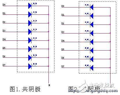
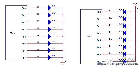
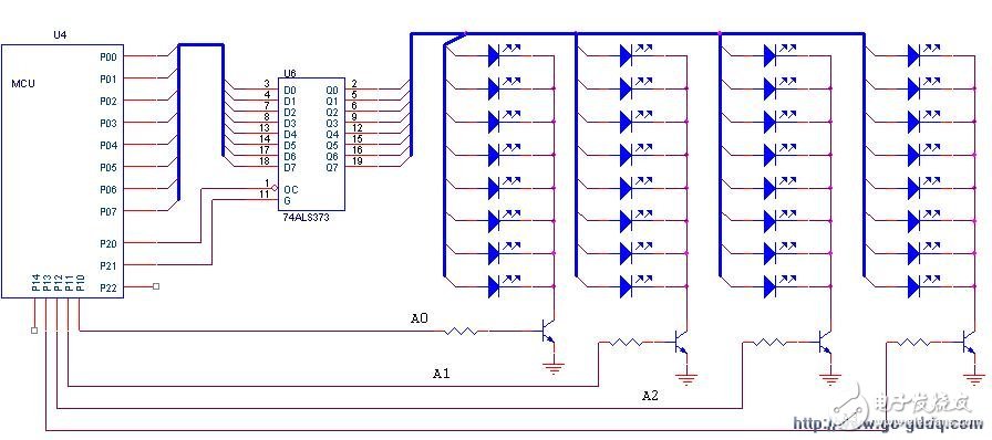
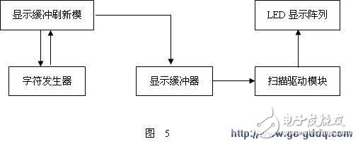
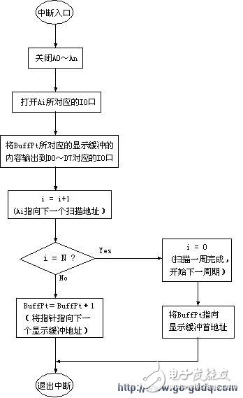
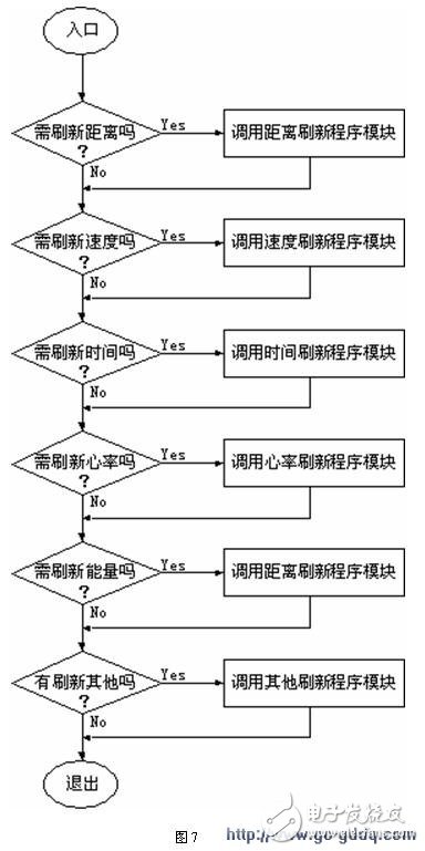
LED (lite EMIt diode) display is a display method often encountered in project development. It has the characteristics of high brightness, full viewing angle, long service life and simple driving. Therefore, it is used on some high-end and large-scale equipment and equipment. widely. The following is a description of the commonly used LED display and driving methods: Led: The LEDs mentioned in this article mainly refer to the following types: l 7-section digital led, divided into two common and common yang, the schematic diagram see 1 and 2; l Commonly used nxm led dot matrix: such as 8x8 led dot matrix module, 5x7 led dot matrix module, etc., which are also divided into two types: common yin and common yang; l Single led tube. The so-called common cathode, that is, the cathodes of all the LEDs are connected together, while the common anode is reversed, and all the anodes are connected together. But no matter which structure, the principle of display design is basically the same, the only difference is that the design of the circuit it drives is different. Generally, the common cathode is driven by push current, and the common anode structure is pulled (pull). ) The way the current is driven. According to the hardware design method of led display, led display driver is divided into two categories: static method and dynamic method. The specific description and programming method are described as follows: The so-called static display driving method means that each led light corresponds to an independent io driving port; its lighting and closing are controlled by the io, and do not interfere with each other, as shown in Fig. 3 (Note: For io driving capability) For weak mcu, it is necessary to add an external driver chip or a device such as a triode. This type of design is generally used when there is a small number of drivers or leds for a single led, and the selected mcu io is relatively abundant. For example, in some projects, the LED indicator and the design of the product only have a 7-segment led code to be displayed. Since each LED is controlled by a separate io port, the software design of the display driver is relatively simple and clear, and no special processing is required, and the level of the corresponding io output port can be set when lighting and turning off is required (ie, “0†or “1†must be determined according to the design of the drive circuit). image 3 Advantages: The circuit design is simple, the programming is simple, and the brightness control of the LED is easy. It is convenient to adjust the brightness by simply adding a corresponding current regulating resistor at the driving end (for the design of the independent driving, the driving voltage can also be adjusted) Adjust the brightness). Disadvantages: Since each led light needs an io port, the demand for the io port is large, and it is difficult to realize a large number of LED driving and display, and the expansion performance is poor. Different from the static display method, the dynamic LED display design method is to connect the driving ends of all the LEDs of different LED modules one to one, as shown in Fig. 4, and the common poles (cathode or anode) are different from each other. Io port to drive (mainly for 7-segment code and led dot matrix module). Here, we call it a common scan line or address line (so the connection method is similar to the internal connection of the memory, each led point is quite a bit in memory), a different led module (similar to a byte in memory) ) Select with different scan line address lines. Figure 4 Since all the LED modules share the drive end, the LED driver is no longer exclusive to each LED as the static method. Therefore, the design method of the driver is completely different from the static method, and it is necessary to use time-sharing scanning (also called dynamic). Scan) method to achieve display driver for all LEDs, the principle is as follows (take Figure 4 as an example): a. Setting a0 to a high level, that is, allowing the first group of LEDs to be displayed, and simultaneously setting a2, a3, a4 to a low level, that is, turning off the display of the led group corresponding to the cathode; b. The display data (also called pattern) corresponding to the a0 group is outputted at the p0 port, such as character dot matrix data, digital data corresponding to the 7-segment code, etc., and the data may be pre-defined by the form of the rom table; c. Maintain a certain time t, which is the interrupt time of the set timer; d. Set the a0 port to low level, and turn off the display of the a0 group led; e. Set a1 to a high level, and the other several are set to a low level to enable the display of the led corresponding to the a1 group; f. Output the corresponding display data of the a1 group at the p0 port (also called pattern, meaning the same as above); g. Repeat the above steps until all the groups are scanned, and then start the next cycle from the a0 group, so that the dynamic display of all the LEDs is realized. 1. The principle of the method utilizes the visual delay of the human eye to the object to achieve simultaneous display of all the LEDs. In fact, at each moment, only one set of LEDs is in the display state, and the other LED groups are in the closed state. In theory, if the time interval between the two displays is less than 32ms, the human eye cannot distinguish. Therefore, in order to achieve this requirement, the scanning frequency of the LED can generally be calculated according to the following formula: f = 32 * n , f is the frequency of the scan, corresponding to the timer's timing time (t=1/f); 32 is converted from 32ms, the frequency corresponding to 32ms is just 32Hz; n is the total number of led groups (n=4 in this example). The scan frequency f calculated according to this formula is actually the minimum frequency of the LED drive scan. If it is lower than this frequency, it may cause the LED to flicker. Of course, f is not likely to be as high as possible, and the scanning frequency is too high. Relatively speaking, the shorter the lighting time of each group of LEDs is, so there may be some problems such as insufficient brightness of LED or unsatisfactory display effect. . Of course, increasing the driving voltage of the LED can also compensate for the problem of insufficient brightness. In this case, it is better to know that the frequency of the scan should be greater than or equal to 128 hz. 2. The implementation of the mcu program: a. Division of modules: Before explaining its programming, explain the application of modular programming ideas in LED driver design. In order to make the structure of the program clear and convenient to maintain, especially in order to make the transplantation of the program become feasible, modular design ideas should be adopted as much as possible in the design process of the program. For the realization of complex program structures and functions, It is better to straighten out the relationship between them before programming, divide the functions that each functional module should complete, and define the data interfaces and relationships between the modules. Generally speaking, the content and functions involved in the display part are relatively wide, such as changes in keys, changes in system status, changes in data, etc., which need to be expressed on the displayed results. Therefore, in order to ensure the independence between different modules, we will divide the functions related to the LED display as follows: 1. Scan driver module: The function of this module only completes the scanning of all LEDs, and does not care about the specific changes of the displayed data. It extracts the data corresponding to each scan address from the fixed display buffer, and the corresponding relationship is fixed. , set by the program design time. The method of implementation is similar to the display driver and display buffer of crt in the PC; 2. Character, dot matrix generator: Since the actual data and the displayed data are not the same, it is necessary to convert the actual data into data that can be displayed. For example, various calculated data in mcu are represented in the form of bcd code or binary code, which needs to be converted into pattern data of 7-segment code or nxn dot matrix for display; 3. Display buffer refresh and processing module: The function of this module is to accept changes in display data caused by buttons, system state changes, and data changes. It needs to call the character, dot matrix generator to complete the refresh of the display buffer, and the interface between it and the button, system state change, etc. is realized by the mechanism of the message. The module generally needs to be classified according to different display contents. For example, in the design of the treadmill, it can be divided into the following contents: distance, speed, time, energy consumption, heart rate and other related data. b. Program architecture and implementation 1. Scan module implementation: Since the LED scan driver is a repetitive and uninterrupted process, naturally, the timer interrupt is the best implementation method. The flow is shown in Figure 6, where bufFPt is used to point to the current display buffer, ai Then, the address number of the led group currently required to be displayed, from 0 to n (n is the total number of led groups); 2. Implementation of the refresh module: In the programming of the mcu, the module is generally placed in a 16hz timed interrupt (this architecture is often used if the main program cycle is not fixed and the maximum cycle time is greater than 1/10 seconds) or In the main program loop body (this case is mainly for the case where the mcu clock is relatively high or when the display delay is not considered), it is determined whether it needs to perform data refresh by detecting the corresponding message. Taking the design of the treadmill as an example, the functional flow is shown in Figure 7; 3. Characters, dot matrix generators: Since in some practical applications, the possible display content is in principle predictable and limited, especially for the display of Chinese characters, it is mainly to save various needs by defining corresponding lattices. Display Data. In order to facilitate the design of the program, it is generally required to be defined according to certain arrangement rules. At the same time, it is necessary to encode the characters and icons that need to be displayed. The coding rules must be beneficial to the design of the program and improve the efficiency of the code. The request can be implemented by using a unified table lookup instruction. Figure 6 Note: The above process is only a schematic program description. In practical applications, the design and simplification of the program should be based on the characteristics of mcu and the specific hardware design. For example, in the actual project, 8x8 (or less than 8x8) LEDs need to be driven, and the selected mcu is 8 or 16 bits. The scanning of the address line at this time will become very simple, as long as it is established. Byte variable ai, its initial value is 0x01, then in each interrupt handler, you need to output ai directly to the io port corresponding to the LED scan line, then move ai left one bit, for 8x8 led case, when When ai=0, it means that the scan is completed once, and then ai is set to 0x01. For the allocation of the displayed buffer, the specific ram address space can also be allocated according to the actual software design to further improve the execution efficiency of the program. Keep in mind that since the scanning of LEDs requires a lot of mcu time, it is necessary to use simple and efficient code in the scanning driver design to improve the efficiency of the mcu. For example, if you need to drive 8x8 led, according to the requirements described above, the required interrupt frequency of the timer must be greater than or equal to 8x32, which is 256hz. If you add one more statement to the driver code, mcu will be used every second. Need to execute 256 more code, which shows how efficient the code is for the led driver, especially when the mcu clock is not fast enough! Cardigan Sweater,Winter Sweater,Color Block Sweater,Turtleneck Sweater Women GUANGZHOU LIWEI ELECTRONICS CO.,LTD , https://www.gdliwei.com