Selection of RS-485 Bus Chips_Applications and Precautions
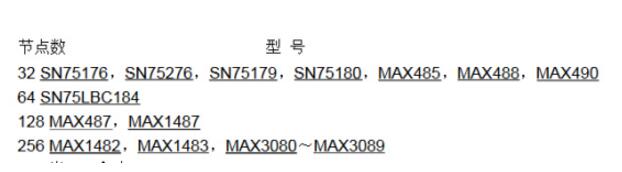
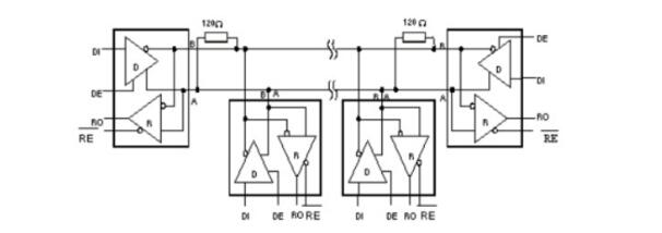
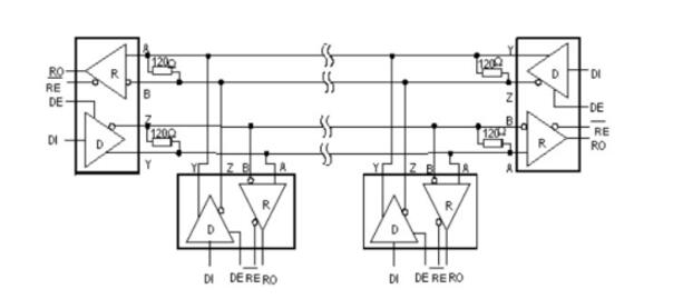
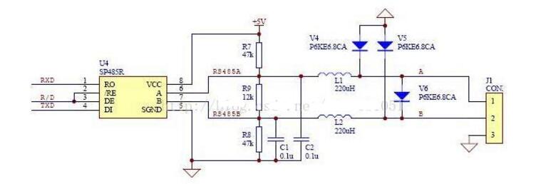
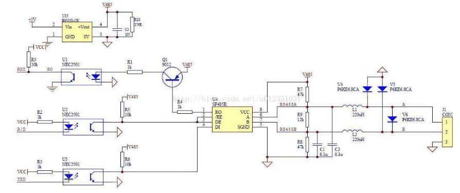
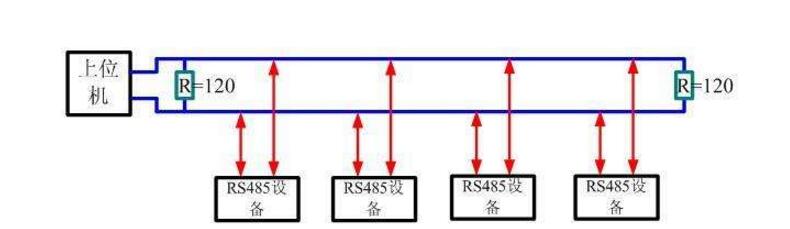
Rs-485 adopts balanced transmission and differential reception to realize communication: the transmitter converts the ttl level signal of the serial port into differential signal a and b, and outputs the differential signal to ttl after receiving the cable. Flat signal. Since the transmission line usually uses twisted pair and differential transmission, it has strong resistance to common-mode interference and the bus transceiver has high sensitivity and can detect voltage as low as 200mv. Therefore, the transmission signal can be recovered beyond kilometers. The maximum communication distance of rs-485 is about 1219m, the maximum transmission rate is 10mb/s, and the transmission rate is inversely proportional to the transmission distance. Under the 100kb/s transmission rate, the maximum communication distance can be achieved, if longer transmission is required. Distance, need to add 485 repeaters. Rs-485 adopts half-duplex work mode and supports multi-point data communication. The rs-485 bus network topology generally adopts a terminal-matched bus structure. That is, using a bus to connect each node in series does not support ring or star networks. If you need to use a star structure, you must use a 485 repeater or a 485 hub. The rs-485 bus generally supports a maximum of 32 nodes. If a special 485 chip is used, it can reach 128 or 256 nodes, and the largest one can support up to 400 nodes. RS-485 bus chip selection RS-485 interface has been widely used in industrial control, instruments, meters, multimedia networks, mechanical and electrical integration products and many other fields. There are more and more types of chips that can be used for the RS-485 interface. How to find the most suitable chip among a wide variety of interface chips is a problem that confronts every user. RS-485 interface in different use occasions, the requirements and use of the chip are also different. The user should consider what factors should be considered in the selection of the chip and the design of the circuit. Some experiences and conclusions in this regard will be given below. The number of nodes, that is how many standard RS-485 loads can be driven by each RS-485 interface chip driver. According to regulations, the input impedance of the standard RS-485 interface is ≥12kΩ, and the corresponding number of standard driving nodes is 32. In order to adapt to the communication occasions of more nodes, the input impedance of some chips is designed to be 1/2 load (≥24kΩ), 1/4 load (≥48kΩ) or even 1/8 load (≥96kΩ), and the corresponding number of nodes can be increased to 64, 128, and 256. The following figure shows the number of nodes of some common chips. The RS-485 interface can be connected to both half-duplex and full-duplex communication modes. The half-duplex communication chip has SN75176, SN75276, SN75LBC184, MAX485, MAX1487, MAX3082, MAX1483, etc.; The full duplex communication chip has SN75179, SN75180, MAX488~MAX491, MAX1482 and so on. (Half-duplex communication method) (Full-duplex communication method) The RS-485 interface chip may be damaged by static electricity when it is used, soldered, or transported by equipment. When the transmission line is used outdoors, the interface chip and the entire system may also be attacked by lightning. The use of anti-static or anti-lightning chips can effectively avoid such losses. Common chips include the MAX485E, MAX487E, and MAX1487E. Especially SN75LBC184, it can not only resist the impact of lightning and can withstand electrostatic discharge shock up to 8kV. Because the signal will produce electromagnetic interference and terminal reflection during the transmission, the effective signal and the invalid signal will be superimposed on the transmission line. If the signal is serious, the communication will not be able to proceed normally. To solve this problem, some chip drivers are designed to limit the slope, so that the output signal edges should not be too steep, so as not to produce excessive high frequency components in the transmission line, thus effectively suppressing the generation of interference. Such as MAX487, SN75LBC184 have this feature. Some RS-485 chips use fault protection techniques such as SN75276, MAX3080~MAX3089. What is fault protection and why is there fault protection? If there is no fault protection, what will happen? As we all know, the RS-485 interface uses a differential transmission mode. Communication between each node is through a pair of (half-duplex) or two-pair (full-duplex) twisted pairs as the transmission medium. According to the RS-485 standard, the receiving sensitivity of the receiver is ±200mV, that is, when the differential voltage at the receiving end is greater than or equal to +200mV, the receiver output is at a high level; when the receiving voltage is less than or equal to -200mV, the receiver output is at a low level. Flat; between ±200mV, the receiver output is indeterminate. When the bus is idle, that is, all the nodes on the transmission line are in the receiving state and when the transmission line is open or short-circuited, the receiver may output high level or may output low level if no special measures are taken. Once a node's receiver generates a low level, the serial receiver (UART) cannot find the start bit, causing communication anomalies. There are two ways to solve this problem: (1) Using a chip with fault protection, it will make the output of the receiver high when the bus is open, shorted and idle. Ensure that the receiver outputs high when the bus is idle and short-circuited is achieved by changing the receiver input threshold. For example, the input sensitivity of the MAX3080 to MAX3089 is -50mV/-200mV, ie when the differential receiver input voltage UA-B ≥ -50mV, the receiver outputs a logic high level; if UA-B ≤ -200mV, the output logic low level . When the receiver input bus is shorted or all transmitters on the bus are disabled, the receiver differential input is 0V, allowing the receiver to output a high level. Similarly, the sensitivity of the SN75276 is 0mV/-300mV, which achieves the purpose of fault protection. (2) When using chips without fault protection, such as SN75176, MAX1487, etc., some processing can be done on the software to avoid communication abnormalities. That is, before entering normal data communication, the bus is driven by the host to be greater than +200 mV in advance and held for a period of time so that the receivers of all nodes generate a high level output. In this way, when valid data is sent, all receivers can correctly receive the start bit and receive complete data. The figure above is the most basic RS485 circuit. When R/D is at low level, the transmission is forbidden and the reception is valid. When R/D is at high level, the transmission is valid and the reception is cut off. Pull-up resistor R7 and pull-down resistor R8 are used to ensure that the non-connected SP485R chip is idle, providing network failure protection, improving the reliability of RS485 nodes and networks, and the three resistors R7, R8, and R9, which need to be changed according to actual applications. Size, especially when using terminating resistors of 120 ohms or less, R9 is not needed. R7 and R8 use 680 ohm resistors. Under normal circumstances, generally R7 = R8 = 4.7K, R9 do not. The clamps located on the 6.8V tubes V4, V5, and V6 are all designed to protect the RS485 bus from outside interference, and can also be integrated with bus protection elements. In addition, L1, L2, C1, and C2 in the figure are optional mounting components to improve the EMI performance of the circuit. The fundamental principle is similar to the basic circuit principle. Using a DC-DC device can produce a set of power outputs that are completely isolated from the microprocessor circuitry to provide +5V power to the RS485 transceiver. The speed of the optocoupler in the circuit affects the communication speed of the RS485 circuit. In the picture above, NEC's optocoupler PS2501 was selected. Under the influence of this, the communication rate of the circuit is controlled at 19200 bps. In the figure above, it is especially important that the TX and RX pins need pull-up resistors. Receive: When there is no data by default, TX is high, the transistor is on, RE is low and enabled, RO receives valid data, and MAX485 is in receive mode. Send: When sending data, TX will first have a pull-down level (start bit - from high to low), indicating the start of data transmission, this time the transistor is turned off, and DE is a high-level transmission enable. When sending data “0â€, because the DI interface is equivalent to ground, the data “0†will be transmitted to the AB deduction, AB “0â€, then transmit “0†to complete the low-level transmission, when sending “1†At this time, the transistor is turned on, and it stands to reason that RO can be enabled. At this time, because the data is still in the sending data, the MAX485 is in a high resistance too. In this state, the state is passed through A, and the B pull-down resistor determines that this time AB 0 transmits "1" to complete the high level of transmission. 1, send and receive timing does not match: 485 is a half-duplex communication. It takes a certain amount of time to send and receive the data. Therefore, there is a corresponding delay between the transmission and reception of the data, and after each frame of data is transmitted. If there is an abnormal transmission or reception, or If a bit error occurs after one frame of data, the delay time can be appropriately increased to see if the problem is solved. 2, R0 pull-up resistor: Asynchronous communication data is transmitted in bytes. Before each byte is transmitted, a handshake is started through a low start bit. In order to prevent the interfering signal from falsely triggering the RO (receiver output) to cause a negative transition, so that the receiver MCU enters the receiving state, it is recommended that the RO external 10kΩ pull-up resistor. 3, a reasonable choice of chips. For example, in order to prevent strong electromagnetic (lightning) shock from external devices, TI's 75LBC184 and other lightning protection chips are recommended. For those with a large number of nodes, the SIP485 SP485R can be used. In addition, our experiments found that ADI's non-isolated 485 chip ADM487E, isolated chip ADM2483, ADM2587 also has a very good performance in multi-node, lightning protection. The 485 bus is widely used in various fields such as video surveillance, access control intercom, and building alarm because of its simple wiring, stability and reliability. However, due to a lot of inaccurate concepts in the 485 bus wiring process, many problems have arisen. Now summarize some common considerations. â— The wiring must be multi-stranded shielded twisted pairs. Multiple strands are used for backup. Shielding is for debugging in special situations. Twisted-pair is because 485 communication adopts differential mode communication principle. Twisted pair has the best anti-interference performance. â— Because the half duplex network composed of RS-485 interfaces generally requires only two connections, the RS-485 interfaces are all shielded twisted pair transmissions. The 485+ and 485- data lines must be twisted with each other. Without twisted pair, it is extremely wrong. The 485 bus must be a hand-held bus structure, resolutely prevent star connections and bifurcated connections. The equipment-powered AC and chassis must be grounded in good condition, and the grounding is good. There are many places with triangular sockets on the surface. In fact, there is no grounding at all. When you are careful about the grounding, you can ensure that the equipment is struck by lightning, and the surge can be matched with the equipment when the static electricity is accumulated. The lightning protection design releases energy well, protects the 485 bus devices and related chips from harm, and avoids walking with strong power to avoid strong power interference. â— There are many devices on the market that use the RS232 interface and the RS485 interface. If there is a 232 interface device that communicates with a 485 interface device, a converter is needed to convert the 232 signal from the 232 interface device to 485. The signal then communicates with the 485 interface device, so the RS232 to RS485 converter becomes the standard configuration of the 485 bus system. â— RS232 to RS485 converter is divided into passive type, active lightning protection, active lightning protection. Passive 485 converters use serial power stealing technology, but due to their small size, many protection circuits cannot be implemented, resulting in poor protection for 485 devices and computers. Due to the serial port stealing technology, the power supply is insufficient, resulting in a small load. Active converters in addition to 232 and 485 conversion, but also to ensure the electrical isolation between the two! Because the 485 line is often long and there is interference on the line, even if there is interference on the 485 line after taking isolation measures, the RS232 interface will not be affected. â— The 485 signal cable must not be routed with the power cable. In the actual construction, because the cabling runs through the pipeline, the construction party sometimes directly connects the 485 signal line and the power cable together for the convenience of the diagram. Because the strong electric signal has a strong electromagnetic signal to interfere with the weak current, Causes the 485 signal to be unstable, resulting in unstable communication. â— It is acceptable to use ordinary super five shielded twisted pair cables. Due to the increase in the price of raw materials, the wire rods and dragons on the market are now mixed, and unscrupulous merchants use some kind of alloy to replace the copper wire to make the network cable, and copper plating on the outside to mix the customers. The specific difference method: Look at the cross section of the network cable. If it is copper, it is copper wire. If it is white, it is filled with alloys. The alloy is generally brittle, easy to break, and the conductivity is far inferior to copper wire, which is very easy to cause problems in the construction. The wire is generally recommended to choose the standard 485 line, which is a shielded twisted pair, the transmission line is not a single strand of copper wire like a cable, but a plurality of stranded copper wire twisted together to form a line, so even if a small copper wire Breaking off will not affect the entire use. â— 485 wiring With 485 hubs and 485 repeaters can be arbitrarily arranged into star-type wiring and tree wiring. The 485 cabling specification is a cabling that must be handed in hand. Once a star connection and a tree connection are directly routed without the help of a 485 hub and a 485 repeater, it is easy to cause signal reflections that can cause bus instability. Many construction parties use star-type wiring and tree wiring in the 485 wiring process. Sometimes the whole system is very stable, but sometimes there are always problems and it is difficult to find the reasons. Generally, it is due to irregular wiring. Caused by. â— The 485 bus must be grounded. In many technical documents, it is mentioned that the 485 bus must be grounded, but no detailed grounding is proposed. Strictly speaking, the 485 bus must have a single point of reliable grounding. The single point is that the entire 485 bus can only have one point grounded and cannot be grounded in multiple points because it is grounded because the voltage on the ground (usually the shielded line is used as the ground) is consistent to prevent common mode interference If grounding at multiple points is counterproductive. When the ground is reliable, the ground of the entire 485 line must have a good contact, so as to ensure the voltage is consistent, because in the actual construction, in order to facilitate the wiring, the line is cut into multiple segments and then connected, but the shield line is not well connected, The ground line is divided into multiple segments and the voltage cannot be kept uniform, resulting in common-mode interference. Gas Stove,Single Burner Gas Stove,Tempered Glass Panel Gas Stove,Stainless Steel Gas Stove Shandong Sangle Group Co.,Ltd. , https://www.sangle-group.com