You can easily do this with the Arduino Uno development board and a breadboard
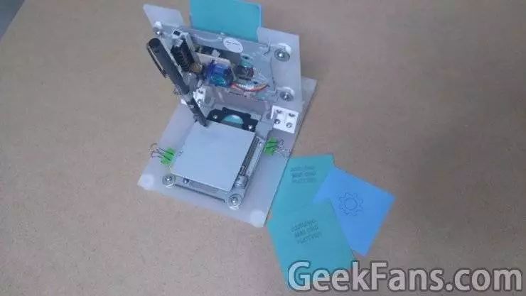
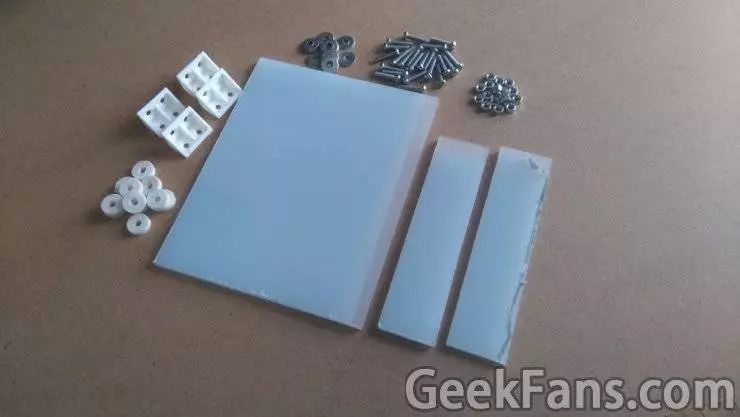
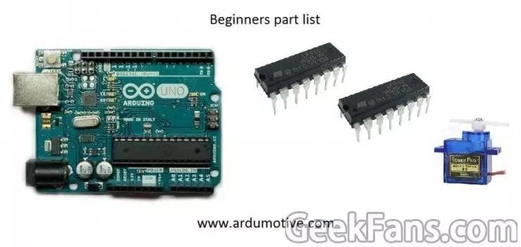
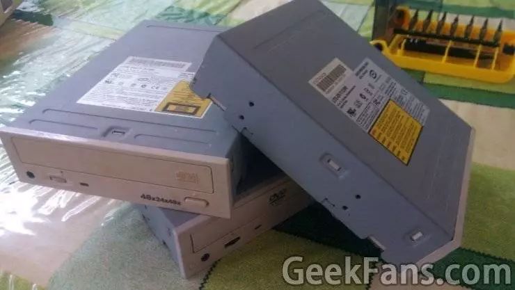
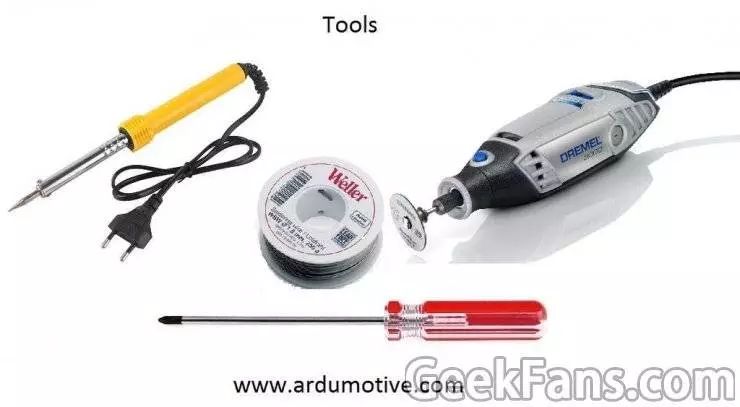
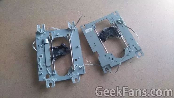
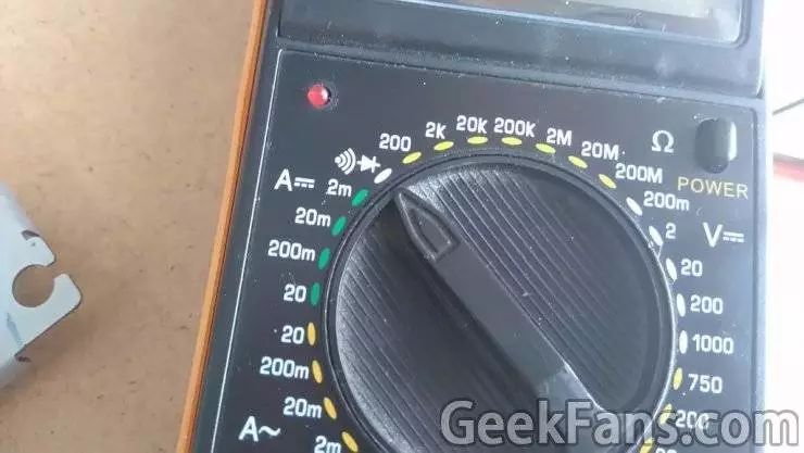
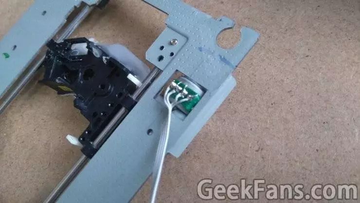
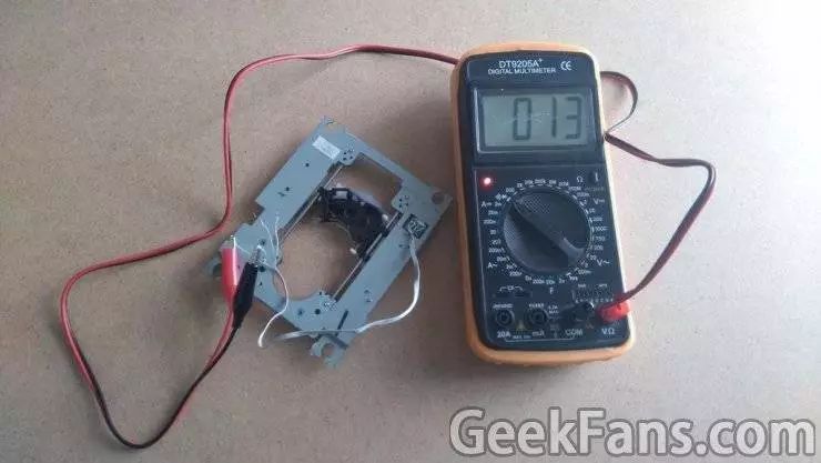
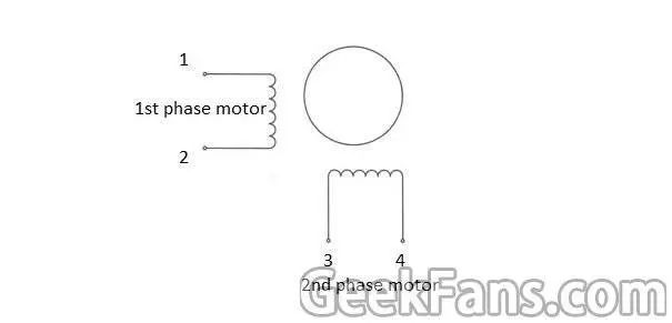
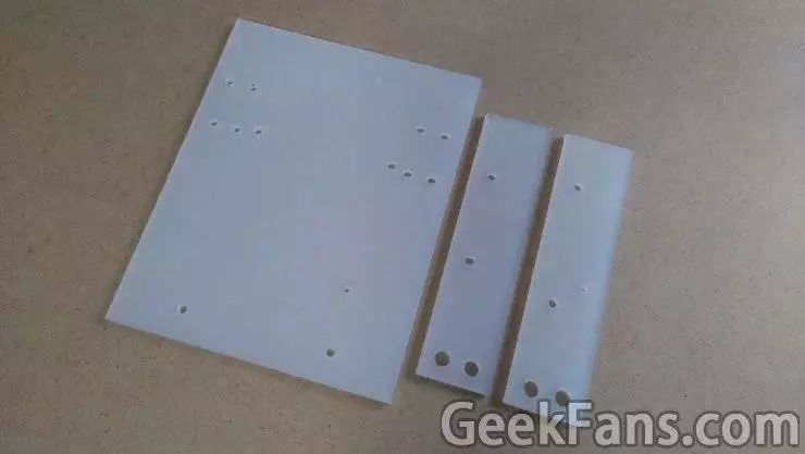
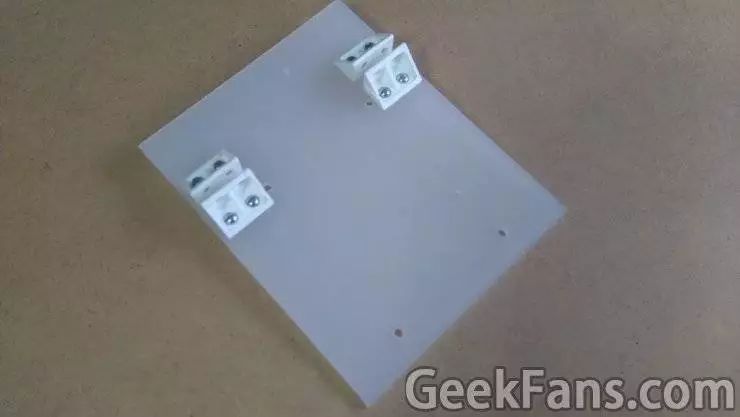
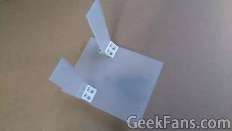
Arduino Mini NC plotter. The plotter in the picture is an improved version. I have made some improvements in the structure and accuracy of the original plotter. After reading this article, I believe you can easily get your own Arduino Mini plotter. Brief description: On the X-axis and Y-axis, we need to use two stepper motors and slides on the DVD/CD drive. On the Z axis, we also use a small servo motor to drive the pen up and down. On the mounting base, we will use resin glass. I wanted to use it as a dual-purpose version of the engraving machine and the plotter, but after several experiments, I found that this machine can only mount the pen, which is a pity. The circuit based on the Arduino board uses the ATmega328 microcontroller, two L293D integrated circuit drivers and a USB serial adapter. You can easily do this with the Arduino Uno development board and a breadboard. Want to print your drawing work? Just add a Bluetooth module just fine. The first step: the required materials Tip: Do not understand the part can refer to the picture. All parts of the hardware are purchased, but I believe that in the universal Taobao can also buy. You need to make circuits Newbie list: Arduino uno Breadboard 2 L293D Integrated Circuit Motor Drivers Mini servo motor 2 DVD or CD drives List of old birds: ATmega328p (Boot to Arduino Bootloader) 28-pin DIP integrated circuit socket 16MHz crystal oscillator Two 22pF and one 100nF capacitors 10k resistors USB serial adapter Two L293D integrated circuits Mini servo motor 2 DVD or CD drives Prototype PCB Board 4 two-pin screw terminal fittings or 2 four-pin screw terminal fittings You also need an Arduino UNO to program the ATmega328 microcontroller. With a USB serial adapter, you can connect a computer and a circuit board like the Arduino Uno. Why use screw terminal fittings? Because we don't want to use the soldering iron before finding the right combination, or welding it wrong can be troublesome. When creating a mounting base you need to: Prepare a 20x16 cm Plexiglass for the X axis (thickness is controlled at about 5 mm). Prepare two 14x4 cm Plexiglas for Y axis (same thickness above). About 20 nuts, screws and washers. Some washers. Four support angles (preferably plastic) If you do not have Plexiglas, you can also use wood, metal or CD and DVD drive trims. tool: screwdriver iron solder Electric drill Cutting tool Strong glue The second step: stepping motor First of all, we have to remove the dvd/cd drive and take the stepper motor off. As shown in Figure 1, use a screwdriver to disassemble it and take the lower rail. Now that we have two stepper motors, we will weld it to the next step. Before you begin, see Figure 2 below. Below we have to find the best route to match, so you can take out the multimeter, clamp the circuit with two alligator clips (as shown in Figure 3), and then place it on the "short circuit" function. In general, the first and second lines will close the circuit, the LED will light up, and the alarm will sound at the same time, but this also means that we have found the first motor, and the third and fourth lines It will lead to the second motor. In this NC plotter, stepper motors with line one and line three are used as the first motor, and lines two and four are used as the second motor. Finding the line with us will begin the next step. Step 3: Mounting the Base, X-axis and Y-axis X axis: First place a stepper motor on a large piece of Plexiglas, and then mark it with a marker to see where it will later be drilled. Make sure that the position is accurate, then use an electric drill to drill holes and tighten the motor with screws. The next step is to turn to the four supporting corners we have prepared. Find a good position for them and mark them with a marker. The interval between them is 5 mm. Then, as shown in Fig. 2, drill eight screw holes for them and secure them with screws. Y axis: Place another stepper motor on the two pieces of resin glass and mark it in detail with a marker. Then repeat the above steps and make four holes in the Plexiglas to fix it with screws. The two pieces of Plexiglas were then placed on the larger Plexiglas glass on the X-axis and then the above steps were repeated to fix them. Pipeline Oil Contamination Detection Sensor This decice is installed in the cooling water line of ship and is designed to detect oil in cooling water.This system consists of oil detection pot,capacitive compact switch and control unit.Oil detection pot for separating oil and water has not cock valve for isolating the input and output line.Capacitive Type Oil Detector is installed in oil detection pot for separating oil and water has not cock valve for isolating the input and output line.Capacitive type oil detection pot,detecting oil Isolated form water on the top of oil detection pot.Control unit receive whether it is deteted or not in signal from the capaciteve compact switch and convert point of contact to relay contact. Pipeline Oil Contamination Detection Sensor,New Ss Oil Pressure Sensor,Oil Pressure Sensor,Ss Oil Pressure Sensor Taizhou Jiabo Instrument Technology Co., Ltd. , https://www.jbcbyq.com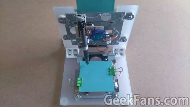


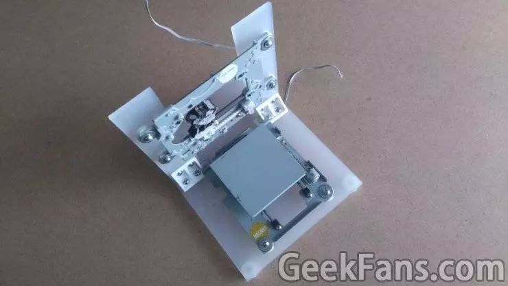
Complete the assembly:
Hit the eyes and fix the screws. Our assembly is completed. I placed a metal plate on the X-axis Plexiglas and put a notepad on it for the plotter. The typical note paper is 75x75mm, but our plotter can only draw pictures of 40x40mm, so you have to modify the size accordingly. Remember, accuracy in this project is very important.
Step 4: Z axis 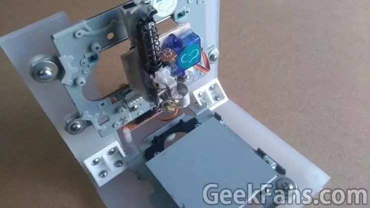
This is probably the most complicated part of the structure.
To install it on the Y-axis, you need a flat surface. In this plane, you have to install the servo motor (Z axis) and pen holder. Under the drive of the servo motor, the pen should be able to move up and down normally. If it is still not clear, please refer to the above figure for understanding. 
Tip: Give full play to your imagination.
Step 5: Circuits The fourth step is taken. The basic hardware part of our production is completed. Now we can start to build the circuit and test the X-axis and Y-axis stepper motors. 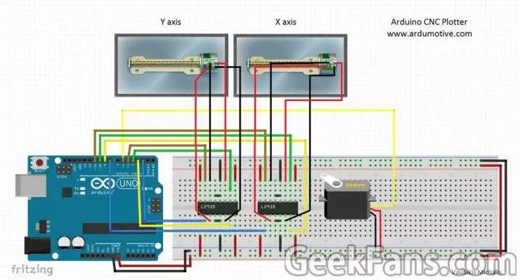
The picture above shows the breadboard circuit diagram.
It takes your patience to complete this step. In the next step, we will also test the X-axis and Y-axis stepper motors. If they are not working properly, you must change the connection of the line in time.
power supply:
A USB interface can not provide enough current, so you have to add a USB cable. After connecting to the power supply, the voltage is still 5V, but the current has doubled. 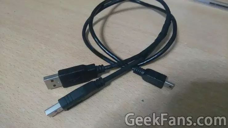
note:
If you want to use other hardware, such as motor end shields or stepper motor drive circuits, you must modify the above circuit and Arduino code. Of course, I cannot do anything about the specific details of the changes. You can search for related tutorials online.
Step 6: Test the Stepper Motor on the X-axis and Y-Axis The following is the code for testing the X-axis and Y-axis. You can use Codebender to embed it in the Arduino development board. 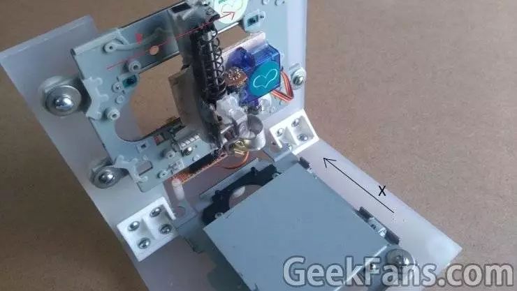
Codebender is an online Arduino IDE. You can program your Arduino development board directly on your browser. Just click the "Run on Arduino" button to start. We highly recommend it.
X axis:
In the test, you have to make sure that the X-axis motor can move from the front to the rear (the black arrow in the figure above).
Code download
Y axis:
In the test, you have to make sure that the Y-axis motor can move from the left to the right (red arrow in the figure above).
Step 7: Numerical Control Code Below are the main NC codes we will use. You can use Codebender to embed it in the Arduino development board.
In this step, your pen will come up. If it does not respond, you have to change the penUp and penDown variables so that the servo motor can be adjusted (just click the Edit button).
Click the "Run on Arduino" button to program your development board from the browser.
The eighth step: GCTRL program 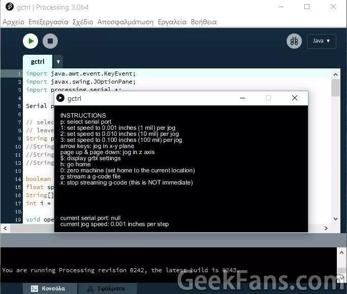
Now we can begin drawing our first painting. But here we also need a handler called gctrl.pde that sends the gcode image to the NC plotter.
So what is gcode? In fact, it is a document that contains the relevant X, Y, and Z axis coordinate information. The coordinates of the header file are set as follows:
M300 S30.00 (Servo motor down)
G1 X20.00 Y10.00 F2500.00
M300 S50.00 (Servo motor up)
You can click on the link to download the handler, then find the relevant software that can open it and click the "Play" button to open the program.
Follow the instructions in the above diagram:
Click 'p' and select your Arduino serial port.
Click 'g' and select the 'TEXT.gcode' or 'gear.gcode' document.
(If something goes wrong, click 'x' to stop the plotter and try again.)
Step 9: How to make your own gcode file To make your own gcode file, you have to use Inkscape.
Inkscape is a free, professional, high-quality vector graphics software. Whether it is Windows, Mac OS X or Linux can run smoothly, it is not only a favorite of professional designers, but also an amateur artifact, you can use the software Make illustrations, icons, maps, logos, etc. Inkscape's native format is W3C open standard SVG, in addition it is an open source software. You can click on the link to download the software (remember to download the 0.48.5 version).
After the download is complete, you need to install an add-on so that the output image can be converted to a gcode document. Below is the download link for this add-on. The software has installation instructions and it is easy to get started. 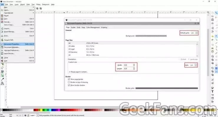
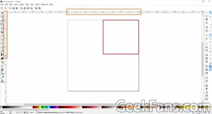

Inkscape settings First, open Inkscape, enter the file menu and click on "Document Properties", then follow the prompts in Figure 1 in the above figure to adjust (remember to adjust the relevant units to centimeters). After setting, you can close the window. Next we will use a blank area of ​​4 to 8 centimeters on the screen (Figure 2).
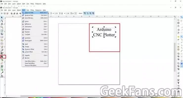
How to draw text With regard to text, you can modify its orientation and size. Steps: Click the cursor to set the size for the text (as shown in Figure 3), select Path on the panel and click "Object to Path" in the drop-down menu.
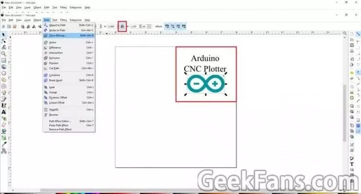
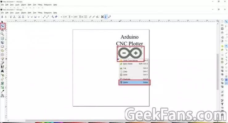
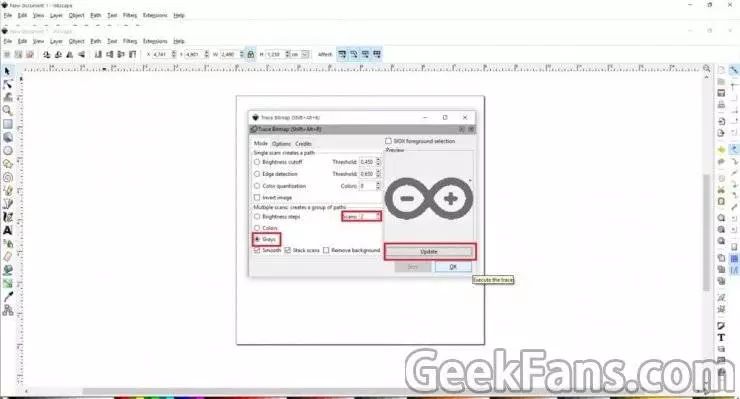
How to draw a picture This step is much harder than drawing text because the background of the picture must be transparent. Drag the picture into Inkscape and click OK to enter the next screen. Now you can adjust the picture size (see Figure 4). Steps: Click on Path in the menu and select "Trace Bitmap", then modify it as shown in Figure 5. Click OK when done and close the window. Then we want to adjust the grayscale and remove its background color. Then click Path again and select "Object to path". Figure 6 will teach you how to delete the image outline.
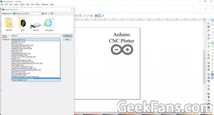
Output in gcode file format Finally, return to the file menu, click Save as gcode file and click OK on the next screen, and you're done. You can then use the gctrl application to plot on your Arduino plotter. 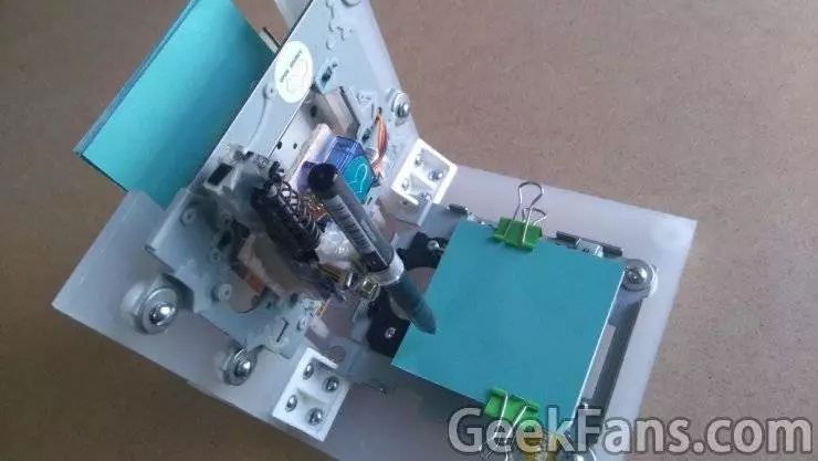
Step 10: Completion If you can follow the above steps step by step, I believe you have made your own CNC plotter, I hope you like it.