Simple motor speed regulation circuit analysis
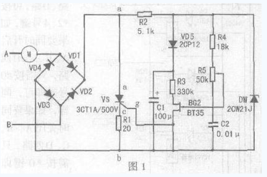
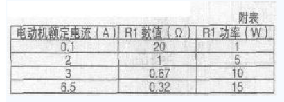
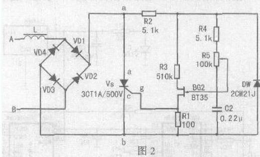
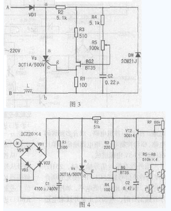
This paper introduces a simple motor speed control circuit that does not require mechanical gear shifting to shift speed, improving the efficiency of mechanical equipment use. This simple electronic speed control circuit is suitable for single-phase motors of 220V mains. The rated current of the motor is less than 6.5A and the power is about 1kW. It is suitable for household electric fans, ceiling fan motors and other single-phase motors. If the circuit is modified, It is used for dimming, electromagnetic vibration regulation, and electric fan temperature automatic transmission. Its circuit is shown in Figure 1. The silicon diode VD1 "VD4 constitutes a bridge full-wave rectification circuit, the bridge is connected in series with the motor in the circuit, and the bridge provides a full-wave rectified voltage to the thyristor VS. When the VS is turned on, the bridge exhibits a low series connection of the motor. When the point A in Figure 1 is negative half cycle, the current forms a loop through the motor, VD1, VS, R1, VD3. When the point B is positive half cycle, the current forms a loop through VD2, VS, R1, VD4, and motor M. The motor end obtains the alternating current. The voltage across the motor is mainly determined by the conduction degree of the thyristor VS. As long as the conduction angle of the thyristor is changed, the voltage drop of the VS can be changed, and the voltage across the motor also changes. To achieve the purpose of voltage regulation, the motor terminal voltage Um=U1-UVD1-Uvs-UR1-UVD3, in the above formula, the voltage drop of UVD1 and UVD3 is small, and the feedback UR1 is not large, so the motor terminal voltage is Simplified to Um=U1-Uvs. The trigger pulse of the thyristor VS is generated by a simple single junction transistor VS circuit, and the capacitor C2 is charged to the stable voltage UZ of the Zener diode DW through the resistors R4 and R5. When C2 is charged to the peak voltage of the single junction transistor, The single junction transistor is triggered to output a pulse to turn the thyristor on. After the emitter voltage of the single junction transistor is sufficiently attenuated, the single junction transistor is turned off, and once VS is turned on, the voltage between the two points a and b falls below the stable voltage UZ of the Zener diode DW, and the capacitor C2 is recharged. Depending on the voltage between points a to b, since the voltage of the Zener diode has dropped below its conduction region, the voltage at points a to b depends on the current of the motor, and the voltage drop when R1 and VS are on. . Thus, when VS is turned on, the charging current of capacitor C2 depends on the current of the motor, and feedback is obtained in this case, which remedies the problem that the torque of the motor is lost at low speed. The value of the feedback resistor R1 is experimentally obtained. Therefore, during the on-period of VS, the capacitor C2 cannot be charged enough to trigger the high voltage of the single-junction transistor. However, the capacitor C2 is charged to the motor current. A value. If the current of the motor increases during a certain on-period, the voltage on C2 also increases, so at the beginning of the next cycle, C2 does not take that long to charge to the peak voltage of the single crystal. In this case, the firing angle is reduced (the conduction angle is larger), and the square root voltage applied to the motor is proportionally increased, resulting in an increase in the effective torque. The diode VD5 and the capacitor C1 prevent feedback due to the triggering of the single crystal during the conduction period, and the value of the feedback resistor R1 is specifically as shown in the attached table. R2 is a current limiting resistor. It should ensure stable DW1 in the regulation range. The steady current is around 10â€20mA. It guarantees the pulse phase shift angle. When R2 increases, the phase shift angle decreases and the voltage regulation range at both ends of the motor decreases. cut back. R4 should guarantee the upper limit of the voltage across the motor. When R4 increases, the upper limit of the voltage output to the motor decreases. R3 is used for temperature compensation of single junction transistor. When R3 is increased, the temperature characteristic is better. This circuit is also suitable for reversible motor speed regulation. The voltage regulation range of the load terminal is continuously adjustable from 35"215V. If the load For the motor or electromagnetic vibration coil, it does not require compensation for the torque, the circuit can be further simplified, the circuit is shown in Figure 2, its working principle is the same as Figure 1, the output voltage main adjustment range is 35" 215V, the role of R1 is To ensure the amplitude of the VS output pulse, if R1 increases, the output pulse also increases. If dimming, the load can be changed to a bulb. If the maximum load voltage does not need to be very high, the bridge rectifier circuit can be changed to half-wave rectification, and the voltage regulation range of the output to the load is 30-100V, and its working principle is the same as before. The electrical schematic is shown in Figure 3. The fan speed control circuit is shown in Figure 4. The circuit uses a thermistor. When the ambient temperature rises or falls, the resistance value changes, causing the VT2 to change continuously, causing the thyristor conduction angle to move back and forth, changing the two fans. The voltage at the end, the speed of the Fan Motor changes. When the ambient temperature rises, the electric fan rotates at a high speed, and vice versa. When selecting components, diode VD1 "VD4 withstand voltage is higher than 400V, rated current is greater than 0.4A; thyristor VS withstand voltage greater than 500V, rated current is 1A; single junction transistor BT35 partial pressure ratio η is greater than 0.5; triode 3CG14 beta More than 80. After the circuit is installed, connect the fan to the circuit, adjust the RP so that the fan stops, and then use a soldering iron to approach the thermistor. When the thermistor becomes high, the fan speed becomes faster. The soldering iron leaves the thermistor, the temperature is lowered, the speed is slow, and the RP should be adjusted to the proper position during operation. Kitchen Range Hood Motor,Range Hood Motor,Kitchen Range Hood,Range Hood Fan Motor WUJIANG JINLONG ELECTRIC APPLIANCE CO., LTD , https://www.jinlongmotor.com