Converter interface isolation method and peripheral circuit introduction
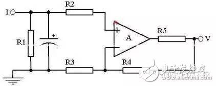
Since the output of the digital-to-analog converter is directly connected to the controlled object, it is easy to introduce interference through the common ground, so isolation measures should be taken. Optocouplers are usually used to make the controller and the controlled object only have optical connections for isolation purposes. The optical coupler is composed of a light emitting diode and a photodiode packaged in the same package, and the input of the light emitting diode and the output of the photodiode have input-output characteristics similar to those of a common transistor. 02 Converter interface isolation method 1. Analog signal isolation method. By using the linear region of the optocoupler, the output voltage of the digital-to-analog converter can be converted into a direct current through the optocoupler, thus realizing the isolation of the analog signal. The output voltage of the converter is converted into an output current by a two-stage optocoupler, which satisfies both the isolation of the conversion and the voltage/current conversion. In order to achieve good transformation linearity and accuracy, two optocouplers with good linearity, the same transmission ratio, and always operating in the linear region should be selected in the application. The advantage of the analog signal isolation method is that only a small number of optical couplers are used, and the cost is low; the disadvantage is that debugging is difficult, and if the optical coupler is not properly selected, the accuracy and linearity of the conversion will be affected. At present, there is an integrated linear coupling chip. In a linear optical coupling chip, there are two optical couplers with good linearity, the same transmission ratio and always working in the linear region. Therefore, there is no difficulty in selecting and debugging with integrated optical coupling. The problem is. 2. The isolation method of digital signals. Using the switching characteristics of the optocoupler, the data signal and control signal required by the converter can be used as the input of the optocoupler, and the output is connected to the digital-to-analog converter to isolate the digital signal. The advantage of digital signal isolation is that the debugging is simple, and the accuracy and linearity of the conversion are not affected. The disadvantage is that the optical coupler using the angle has a high cost. 03 Overview of I/V Transformation Many transmitters have an output signal of 0 to 10 mA or 4 to 20 mA. Since the input signal of the A/D converter can only be a voltage signal, if the analog signal is current, the current must be turned into a voltage before A/. D conversion. This requires an I/V conversion circuit. Let's discuss the implementation of I/V transformation. (1) Passive I/V conversion: Passive I/V conversion is mainly realized by using passive device resistance, and adding protection measures such as filtering and output limiting, as shown in the following figure. For 0~10mA input signal, R1=100, R2=500, and R2 is a precision resistor, so when I is 0~10mA current, the output V is 0~5V; for 4~20mA input signal, R1= 100, R2 = 250, and R2 is a precision resistor, so when the input current is 4 ~ 20mA, the output V is 1 ~ 5V. (2) Active I/V conversion The active I/V conversion is mainly realized by using active device operational amplifiers and resistors, as shown in the following figure. The magnification of the in-phase amplifier circuit is: A=1+R4/R3 If R3=100KΩ, R4=150KΩ, and R1=200Ω, the 0~10mA input corresponds to the voltage output of 0~5V. If R3=100KΩ, R4=25KΩ, R1=200Ω, the 4~20mA input corresponds to the voltage output of 1~5V. 04 Preamplifier circuit The task of the preamplifier is to amplify the small signal of the analog input into the range of the A/D conversion. In order to adapt to the amplification requirements of many small signals, a variable gain amplifier can be designed. Some of today's transmitters output standard voltage signals or standard current signals. Preamplifiers are not commonly used in A/D converter circuits. 05 multi-channel analog switch The multi-channel analog switch is a circuit that selects the input channel analog input signal required from a plurality of analog input signals. Field effect transistors are widely used as analog switches. The advantage is that the working speed can reach 10 times 6 times / 3, the on-resistance is low (5 ~ 25 ohms), and the cut-off resistance is up to 10 10 ohms. 06 Principle of sample and hold circuit The sample and hold circuit is capable of tracking or maintaining the level value of the input analog signal. Under ideal conditions, when in the sampling state, the output signal of the sample-and-hold circuit changes in accordance with the change of the input signal; when in the hold state, the output signal of the sample-and-hold circuit remains at the input signal level value at the moment of receiving the hold command. . When the circuit is in the sampling state, the switch is turned on. At this time, the capacitor is charged. If the capacitance value is small, the capacitor can be charged and discharged in a short time. At this time, the output signal of the output changes according to the change of the input signal; When the switch is in the hold state, the switch is disconnected. This is because the switch is open and the input of the integrated op amp is in a high-impedance state. The capacitor discharges slowly. Since one end of the capacitor is connected to the signal follower circuit formed by the integrated op amp, the output signal is basically maintained. To disconnect the instantaneous signal level value.
The sound quality of small speakers is also good. It does not have the same large speakers and power as HIFI speakers, and its sound quality cannot compete with large speakers due to physical limitations. But for the vast majority of users who are not golden ears, the use of small speakers with tablets and mobile phones is sufficient to meet their hearing needs.
Retro Speaker,Bluetooth Retro Speaker,Rechargeable Retro Speaker,Portable Retro Speaker Shenzhen Focras Technology Co.,Ltd , https://www.focrass.com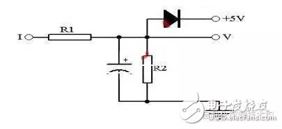
For Bluetooth retro speakers, I personally think that when many people buy speakers, the appearance is the first priority and the function is second.
We focus on retro Bluetooth speakers,It has high energy density, mini size, light weight and diversified shapes;Excellent fast charging performance, support fast charging and other excellent features
with a brand-new design, showing retro nostalgia without losing fashion. It uses a 2.5-inch speaker and has many functions such as FM radio, Bluetooth fast connection, multi-mode switching, and HIFI high fidelity. Wireless Bluetooth 4-10 hours of playback (at 50% volume), which adds to its unique charm.