Three-dimensional electromagnetic analysis based on low frequency band VHF and UHF
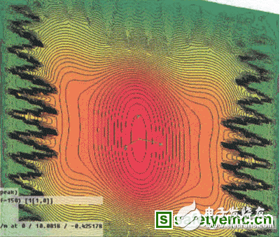
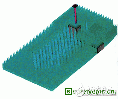
It is well known that microwave darkrooms have the advantage of being safe, without radiation interference and unaffected by weather factors when performing antenna measurements compared to outdoor fields. A typical microwave darkroom includes a shield having an inner surface covered with a absorbing material, a source antenna and a body to be tested (DUT), and a turret system that can be rotated to obtain a DUT antenna pattern. The size of the shielded shell is mainly determined by the minimum operating frequency. When the darkroom is operated in the VHF and UHF bands, the required size is significantly increased, thus increasing the cost of the darkroom structure and the required absorbing material. The minimum operating frequency of the darkroom is The advantages of the VHF and UHF bands are lost compared to the outdoor field. In this case, people pay attention to the actual real demand of the darkroom structure, and choose a compromise to reduce the cost of the darkroom and increase the size of the darkroom to ensure the minimum performance level, in order to ensure the minimum level of antenna measurement accuracy. The quality of the illuminating wave in the DUT test area and the reflection in the dark room must meet the standard. This requires the darkroom supplier to accurately analyze the darkroom performance and make the designed darkroom the most cost-effective. For a long time, the engineering analysis of the darkroom has always used the ray tracing method, but the darkroom size is only a few wavelengths at the lowest operating frequency, so the accuracy is very poor, and the factors causing the accuracy are as follows: ◠The reflection of the mirrored area is sufficient to affect the quality of the DUT test area. The characteristic area of ​​the mirrored area has several wavelengths. The surface covered absorbing material even exceeds the darkroom side wall, ceiling and ground in the VHF and UHF bands. Feature size. ◠The effective mirror area is large, and it is difficult to determine the exact incident angle of the mirror when using the ray tracing method. ◠It is difficult to accurately predict or predict the reflection coefficient of the wall absorbing material when it deviates from the vertical projection at low frequencies. ◠It is difficult to accurately measure the phase of the reflection coefficient of the absorbing material. Therefore, only the effective value (RMS) of the DUT test area field and the square root value (RSS) of the sum can be calculated, so that only an approximation can be provided. • In the VHF and UHF bands, many cases are approximated based on the decreasing curve of the reflection coefficient of the absorbing material at oblique incidence above 2 GHz. This extrapolation method is quite inaccurate for many darkrooms. The most effective improvement to the ray tracing method is the aperture integration method, in which the reflection field reflected from the side wall into the test area is calculated using Kirchhoff integrals of the entire diameter (including side walls, ceilings or floors). The field in the test area is the superposition of the reflection field and the radiation field of the source antenna. Although this method is better for darkroom analysis, the accuracy obtained is still limited due to the reflection coefficient of the absorbing material used in vertical and oblique projection (the amplitude and phase of the two cross-polarizations). limits. As mentioned earlier, the UHF and VHF bands are even more problematic. In addition, both the aperture integration method and the ray tracing method cannot calculate the multiple reflections in the dark room of this frequency band, but this is very important. The lack of accuracy estimates for darkroom performance may result in a darkroom design that is not optimal. However, it is not always the best performance to judge. For example, field detection in the test area may also indicate the appearance of no changes and fluctuations. This is due to the fluctuation of the interferogram caused by indoor surface reflection and direct reflection at low frequencies. The reason for the longer cycle. In order to ensure proper darkroom performance, the darkroom field strength detection should be performed in the entire frequency band as possible. The field-like zigzag fluctuations over the entire frequency band in the test zone should be marked. Multiple matches are adjusted to transmit and receive polarization throughout the frequency band. The small fluctuations in the recorded signals indicate that the performance of the darkroom is better. The aforementioned analysis techniques are restrictive for low frequencies, and it is obvious that comprehensive analysis is required strictly. The more suitable analysis is the three-dimensional electromagnetic simulation method described below. Not long ago, there was no standard software package for 3D quantitative analysis of darkrooms for solving such problems, but recently with the advancement of PC computer technology, there has been a computational simulation software package for 3D electromagnetic analysis using time domain method technology, which makes this analysis change. It is possible. ORBIT/FR has successfully completed the performance simulation of the low frequency darkroom with a commercial conversion solution software package. Typical simulation results for low frequency darkroom performance simulated using 3D time domain techniques are described below. The primary analysis is to analyze the field uniformity of indoor locations of interest, such as the amplitude taper and ripple, phase changes, and resulting cross-polarization levels in the DUT test zone and subsequent darkrooms. These quantities are related to the following parameters: ◠The layout and quality of the absorbing materials. ◠Source antenna/DUT spacing. ◠Working frequency. ◠Source antenna beamwidth. ◠DUT turntable situation. ◠DUT support structure shape and material condition. These analyses provide information about the distance and location of the source antenna from the DUT, and the layout of the absorbing material, so that the minimum size of the darkroom can be achieved to achieve the desired performance. The most effective method for darkroom simulation is to create standard databases of various types of absorbing materials, such as pyramid materials, wedge materials, composite materials (such as pyramidal back composite ferrite tiles), and absorbing floor materials. Each type of material has a different size, such as a pyramid material from 5 cm high to 2.4 m high, with a higher height for the UHF and VHF bands, typically 0.9 to 2.4 m. The load characteristics of the material are input and stored in a database based on measurements of material properties ε′(f), ε′′(f), μ′(f), μ′′(f) for the entire frequency band. The precise nature of the material is one of the most important parameters for simulation. Figure 1 a isometric view of the darkroom design b absorbing material on the floor layout Product categories of Cloth Pen Nib, it is belong to Passive Stylus Pen. Passive stylus pen is characterized by being cheap and without charging. But compared with the active capacitive stylus pen, its tip diameter is larger, so it cannot be used in works with high precision. Using high-quality conductive cloth head, smooth contact with the screen. Cloth Pen Nib,Multi-Functional Pen Stylus Pen,Stylus Pencil With Clip,Touch Stylus Pencil Shenzhen Ruidian Technology CO., Ltd , https://www.szwisonen.com