Discussion on the Design of Automobile Radar Based on Radio Frequency Technology
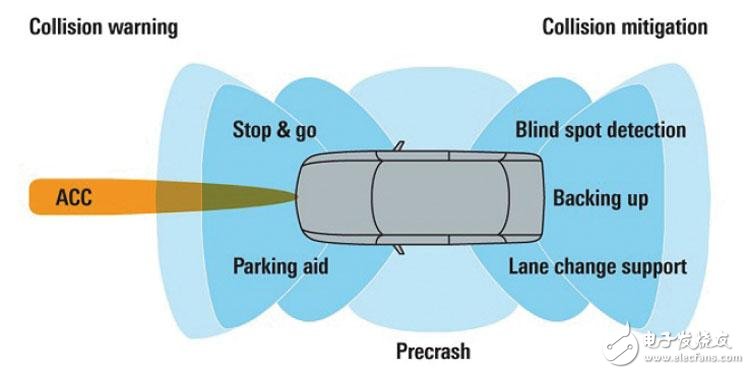
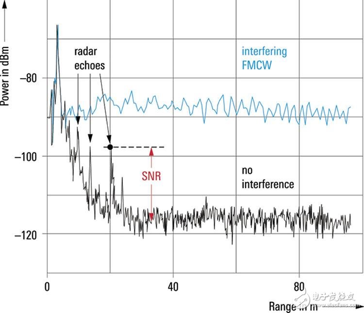
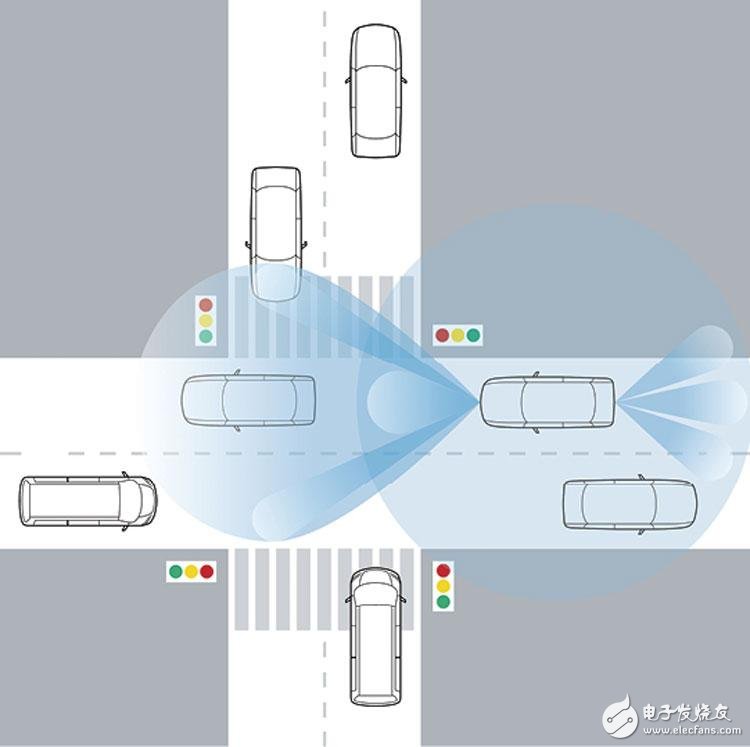
Automotive radar technology is on the rise. Whether it is the blind spot detection at this stage or the development of automatic driving control, high performance, high reliability, compact and low cost are the indispensable factors and motives to promote the continuous development and improvement of automotive radar core technology. Automotive radar is an important part of the driver assistance system. It not only provides a comfortable driving environment to reduce the tension, but also lays a necessary foundation for improving road traffic safety. From the design of automotive radars to their optimization to mass production and installation, a variety of inspection and measurement methods are used. This paper discusses some design points of automotive radar from the perspective of radio frequency (RF) measurement technology. Similar to other radar technologies, automotive radars also rely on the reflected signal of the receiving target object and further analyze the multiple correlations between the received signal and the original transmitted signal in time, frequency and phase to determine the target object and the radar. Relative speed and spatial position. One of the core technologies of automotive radar is radar waveform design. Linear frequency modulated continuous wave (LFMCW, often referred to as FMCW) is a commonly used radar waveform. The stability and linearity of the transmitted signal (ie, the waveform) directly affect the ability of the radar to identify the target object. Since most of the automotive radars operate in the millimeter wave band, the inherent nonlinear characteristics of the various materials and components selected will be incorporated into the final transmitted and received signals, thereby interfering with the signal analysis algorithm. The car radar uses the frequency difference and phase difference between the transmitted signal and the received signal to determine the speed and position of multiple target objects. When the linearity of the entire radar system, especially the transmitter part, exhibits non-ideal characteristics, the calculation results of the frequency difference and the phase difference will be ambiguous, causing the radar system to fail to correctly judge the target object, so that a major error occurs. For future autonomous driving control technology, this is absolutely to be avoided. In order to minimize the error rate, the linearity of the transmitted signal must be increased as much as possible, and the stability of the linearity of the product is ensured by measurement. Based on the stringent requirements of signal quality, linearity measurements mostly use high-end instrumentation to reduce measurement errors. Today's high-end instruments can analyze signals with bandwidths greater than 1-GHz to ensure complete measurement of radar signals. Car radar is expanding rapidly, providing more driving assistance and higher safety for vehicles In automotive radar applications, either a transmit antenna or a receive antenna, a phased array is typically used. Linear arrays or planar arrays can be used as needed for the overall design. It is well known that the main parameters of an array antenna (eg, main lobe direction and width, sidelobe suppression, zero position, etc.) can be calculated by simple mathematical formulas. However, the applicability of such calculations is conditional, that is, when the mutual coupling and effects between any two units in the array are extremely small to negligible. There is a way to satisfy the above conditions by increasing the relative distance between the array elements. However, the impact of this approach is that the size of the end product will also increase. If it is not possible to achieve an efficient and accurate design of the array unit by calculation, the measurement becomes an important means in the optimization process, and then the corresponding computer software is used as an aid to facilitate the big data operation. The optimization of array antennas is usually divided into the following steps: · Radiation pattern design of array basic unit · Evaluation of mutual coupling between array units · Radiation pattern design of antenna array · Array feed system design · Radar transceiver system integration design · Vehicle bumper impact consideration In addition, the overall design of the radar system must also include the requirements for safety and convenience. The safety and convenience will directly or indirectly affect the design of the antenna. In the design of the array base unit, especially in the evaluation of the mutual coupling between the array units, since the phased antennas usually have a large number of array units, complete, accurate and fast measurement becomes the most critical factor. To achieve complete and accurate requirements, multi-port vector network analyzers are essential. Taking into account the requirements of safety and convenience, the radiation field stability of the same batch of automotive radar products is crucial. To achieve this goal, the radiation field measuring equipment must first have good repeatability of the measurement results. This is also one of the difficulties in automotive radar measurement technology. In general, the measurement of the antenna radiation pattern must be performed in the far field. The far field here is a relative concept. According to the definition of antenna measurement theory commonly used in the industry, the far field is related to the size of the antenna to be measured and the operating frequency range of the antenna. Specifically, the far field of an antenna is proportional to the square of the largest dimension of the antenna and inversely proportional to the operating wavelength of the antenna. For example, the maximum size of an automotive radar product is 7.5 cm, and if its operating frequency is at 24 GHz, the far field is about 0.9 m away. But if it works at 77GHz, its far field will expand to about 3m. Under normal mass production conditions, such a large distance range is almost impossible to achieve. In order to overcome the limitations of the far field definition described above, data acquisition can be performed in the near field, and then the acquired data is converted into the far field result by the correspondence between the near field and the far field. Although this near-field measurement method no longer has a limitation of the range of distance, in order to ensure the accuracy of the measurement results, not only the measurement equipment becomes quite complicated, but also the time required for data acquisition is multiplied. In addition, because the data conversion requires extra time, the entire measurement process becomes very lengthy, so that it is difficult to meet the requirements of mass production performance. The industry is currently investigating new ways to minimize these space and time constraints to increase mass production capacity over an appropriate distance. Like other RF products, there are also interference and anti-interference problems for automotive radar. From the current technology, there are more than ten radars on a single car. Fortunately, thanks to the design of the antenna and the appropriate adjustment during installation, the mutual interference between the individual radars on a single vehicle can be reduced. However, there is currently no design technical standard related to automotive radar. The frequency range in which the automotive radar operates does not require a permit. Therefore, the mutual interference between the radars of different vehicles, especially the vehicles of different manufacturers. It can be a very difficult problem. In view of the existence of too many unknown factors related to the source of interference, in the design stage of anti-interference ability, from the worst point of view, taking into account the scenes that initially appear to be less probable, in order to correctly assess the radar system is disturbed and make unpredictable reaction. As mentioned earlier, automotive radar is primarily used to accurately and quickly determine the relative velocity and spatial position between the target object and the radar. Wrong judgments can be divided into two broad categories: one is "magic", that is, "out of nothing"; the other is "blind", that is, "turning blind." Regardless of the type of misjudgment, it is closely related to traffic safety. For future automatic driving control technology, these are absolutely to be avoided. If the relative distance is far enough, there will be sufficient time to correct the misjudgment. Therefore, misjudgment at relatively close distances will be very dangerous. How should we evaluate "relative close distance"? For example, on a road in an urban area, the usual speed limit is 60 km/hr. At this speed, 15m to 20m will be "relatively close". Because once a traffic anomaly occurs within this distance, the radar system must quickly and efficiently activate the braking system to allow the moving vehicle to stop in a second or less. But the question is, can the above-mentioned "magic vision" or "blindness" occur in the radar system within this distance? The answer is yes. That is to say, because the receiving system is disturbed, under certain conditions (even including the influence of the weather), the sensitivity of the car radar system to the signal reflected from the target object will drop sharply, and the target object outside the original 100 meters can be distinguished. At this time, even a target object of about ten meters is difficult to recognize. In order to ensure the anti-jamming capability of automotive radars, standardized measurement methods are necessary. Although there are no measurement regulations at present, the industry can refer to other similar standards, first carry out the previous reliability measurement, and thus win the time advance measurement, so that after the formal measurement method is standardized, based on the existing data, the anti-correction is appropriately adjusted according to the regulations. Interference margin, or improve anti-interference ability. The current anti-interference ability detection method mainly uses software to set the scene. In the anechoic chamber, a specific radar waveform is generated by the signal source as the interference source, and then the radar target simulator simulates a specific target object, thereby evaluating the radar under test. The degree of decline in the sensitivity of the target object's reflected signal in this particular scenario, thereby estimating the anti-jamming capability of the radar under test for a particular interferer in this particular scenario. Different types of automotive radar sensors share a limited unlicensed spectrum and may interfere with each other In summary, due to the extremely important traffic safety factors, before the automatic driving control technology truly becomes a part of people's daily life, one of the key technologies of radar technology needs further development and improvement, for example, radar waveform. Stability of linearity, technical bottlenecks in mass production, anti-interference ability in various scenarios, etc. The radio frequency measurement technology of automotive radar, which is closely related to this, has laid the necessary foundation for accurate testing and more advanced measurement requirements in the future. docking station for macbook air,docking station for laptop,docking station usb c,USB C HUB,thunderbolt 3 usb type c hub Shenzhen Konchang Electronic Technology Co.,Ltd , https://www.konchang.com