How the combiner works (technical indicators, testing and classification)
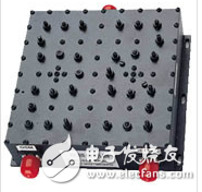
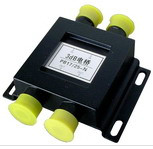
The combiner is generally used for the transmitting end, and its function is to combine two or more RF signals sent from different transmitters into one RF device that is transmitted to the antenna, and avoid mutual influence between the respective port signals, as shown in the figure. 1 is shown. Figure 1 combiner physical map A combiner typically has two or more input ports and only one output port. Port isolation is an important indicator to describe the ability of two signals to not affect each other. Generally, it is required to be above 20dB. The 3dB bridge combiner has two input ports and two output ports, as shown in Figure 2. It is commonly used to combine two wireless carrier frequencies and feed them into an antenna or distribution system. If only one output port is used, the other output port needs to be connected to a load of 50W, and at this time, there is a 3dB loss after the signal is combined. Sometimes both output ports are used, and no load or 3dB loss is required. Figure 2 3dB bridge combiner Combine the receiving and sending of the signal phone to an antenna. In the GSM system, since the transceiver is not in the same time slot, the mobile phone can eliminate the duplexer for isolating and transmitting, and can combine the sending and receiving signals into one antenna by using a simple transceiver combiner. Up and without interfering with each other. For the receiving circuit, the antenna receives the signal, enters the receiving channel through the combiner, mixes with the receiving local oscillator signal (ie, the receiving VCO signal generated by the frequency synthesizer), turns the high frequency signal into an intermediate frequency signal, and then performs the signal. Quadrature demodulation produces received I and Q signals; then GMSK (Gaussian Filter Minimum Shift Keying) demodulation is performed to convert the digital signal analog signal into an analog signal, which is then sent to the baseband processing unit. For the transmitting circuit, the TDMA frame data stream (rate 270.833 kbit/s) is sent by the baseband part to perform GSMK modulation to form the transmitting I and Q signals, and then sent to the transmitting up-converter to modulate to the transmitting frequency band, and the power is amplified and combined. The device is transmitted by the antenna. The frequency synthesizer provides the local oscillator signal necessary for the frequency conversion of the transmitting and receiving units, uses a phase-locked loop technique to stabilize the frequency, and obtains a frequency reference from the clock reference circuit. The clock reference circuit is typically a 13 MHz clock that provides a clock reference for the frequency synthesis circuit on the one hand and a working clock for the logic circuit on the other hand. 1. In mobile communication, due to the sharing of multiple channels, in order to avoid intermodulation interference caused by radio frequency coupling between different channels, and considering the factors of economy, technology and erection site, the antenna duplexer should be used for transmission. 2. The combiner consists of a cavity resonator and a circulator, which is a high Q value, low insertion loss bandpass filter. The circulator is a three-fault device with a small forward loss (0.8dB) and a large reverse loss (20dB). 3. In order to enhance the stability of the combiner work, the internal matching technology is generally used to connect the cavity without a flexible cable. In order to reduce the volume, a square cavity structure is generally used. 1. Insertion loss, 4 channels are usually less than 3.6dB, and 8 channels are usually less than 4.0dB; 2. Inter-channel isolation, usually greater than 80dB; 3. Output and input port isolation, usually greater than 80dB; 4. Frequency drift, usually not more than 3ppm after one year of aging; 5. Input standing wave ratio, less than 1.5dB Thin Wafers,Silicon Wafers,Glass Wafers,4 Inch Wafers Zoolied Inc. , https://www.zoolied.com