FPGA-based infrared home remote control system
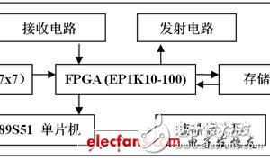
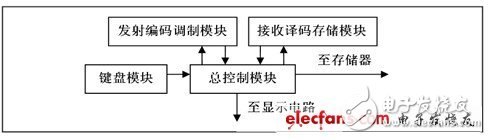
The types of household appliances in people's lives are increasing, and the types of remote controls are also increasing. Different types of remote controllers cannot generally replace each other, which brings inconvenience to people's lives. The functions of various remote controls are roughly the same. Most of them have numeric keys, start stop buttons, forward buttons, fast forward buttons, and back buttons. The complicated ones are to add several function keys. In real life, due to individual differences of users, special functions. The use of keys is very low, and even some users have never used such keys from start to finish. Therefore, these keys can be simplified and categorized. For a small number of special function keys that are not easy to simplify and categorize, you can customize them. The method of the button area is solved. Infrared is an electromagnetic wave having a wavelength between 0.75 μm and 100 μm. Its frequency is higher than that of microwave and lower than visible light, and it is a kind of light that is invisible to human eyes. Infrared communication generally uses near infrared rays in the infrared band, and the wavelength is between 0.75 μm and 25 μm. After the establishment of the Infrared Data Association (IRDA), in order to ensure the best communication results of infrared products from different manufacturers, the infrared communication protocol limits the wavelength of light waves used in infrared data communication to 850 nm to 900 nm. The control codes used for remote control are mostly modulated with a different coding standard above the carrier frequency of about 38 kHz, and then transmitted in the serial format through the on and off of the infrared carrier. The system adopts the structure of "computer host + single chip + FPGA". The system software is divided into two parts: one part is the Girder program running on the host, used to decode the received signal and control the computer to perform the specified action, and the other part runs on On the single-chip microcomputer, it is used to drive the liquid crystal (LCD) display of the remote control. The hardware of the system is divided into four parts: the learner, the trainer, the receiver and the interface circuit with the host. The learner has the functions of learning and remote control. By learning the code of the original remote control, it can remotely control any electric appliance with remote control function. It includes two parts of the MCU and the FPGA. The main learning and remote control functions are performed by the FPGA to improve the running speed and integration. The MCU is used to drive the LCD display; the trainer and the receiver are responsible for adding the remote control function to the device without the remote control function. Specifically, the trainer generates a sufficient number of encoded addresses for the learner to learn, and the receiver is responsible for decoding the corresponding address and generating corresponding actions at the electrical end; responsible for implementing the host interface circuit designed for remote control of the computer Convert the infrared signal to a digital signal and send it to the host. The overall block diagram of the hardware circuit implementation is shown in Figure 1: Figure 1 Overall block diagram of the hardware system The learner is the main part of the hardware circuit, and has the functions of learning and remote control. It takes FPGA as the core and the peripheral circuit is simple. It mainly consists of keyboard, memory, receiving circuit and transmitting circuit, considering the use of pure hardware to control the LCD display. The difficulty is large, decided to use the microcontroller to assist the FPGA to achieve. The receiving circuit here is different from the receiver to be mentioned later. It is specially designed for the learning function. It is responsible for receiving the infrared signal of the existing remote controller and sending it to the FPGA for identification, decoding and storage. The transmitting circuit is driven by the driving circuit and infrared light. The diode consists of two parts of the circuit, which is responsible for transmitting the encoded signal in the form of infrared light. Figure 2. Learner hardware structure It includes three modules: keyboard module, transmit code modulation module, receive decode memory module, and another total control module. Its internal structure is shown in Figure 3: Figure 3. FPGA internal structure The total control module is a finite state machine, which is responsible for coordinating the work of other modules and providing an interface with the display circuit and the memory; the keyboard module receives the user's button information and encodes the output to the total module, including the address of the button, the button The type and the user select the device code to be remotely controlled; the receiving decoding memory module records the width of the high and low levels of the received signal by the counter, and stores the data in the corresponding address of the memory, the storage timing is controlled by the state machine; the transmitting code modulation module is responsible for The data information of the current button is read from the memory, and a level of high and low variation similar to the learned signal is generated, and the output is modulated with a carrier of 38 kHz.
Good DC immune component core
The resisting DC iron core has strong resistance DC component ability, wide current range, few additional circuits and devices, strong reliability and insensitive to interference.
The resistance DC composite single magnetic core is a single resistance DC magnetic core, which has the characteristics of high linearity, high precision, easy phase error compensation and good high and low temperature characteristics. At the same time, compared with the composite core, the single core has stronger stability and smaller volume.
Our excellent magnetic iron core has high permeability,low coercivity and loss,excellent performance on DC immue and temperature stability that can be widely used to the electronic watt-hour meter,resistance DC component transformer and electrical power system measurement.
Anyang Kayo Amorphous Technology Co.,Ltd. , https://www.kayoamotech.com
In view of this, this paper designs a self-learning universal home remote control based on the idea of ​​recording waveforms based on single-chip microcomputer and large-scale programmable gate array FPGA, and adds equipment for electric lights, fans, curtains and other facilities without remote control function. The remote control model of the coach + learning + control can also realize remote control of the computer after installing the Girder software on the computer.
Since the infrared wavelength is short and the diffraction ability to obstacles is poor, it is suitable for point-to-point linear data transmission where short-range wireless communication is required.
Here's a quick introduction to common coding standards:
1) Pulse Coded (Pulse Coded)
The length of the pulse differs depending on the indicated data '0', '1', and Sony's remote control uses this code.
2) Space Coded (Space Coded)
In contrast to pulse coding, it is based on the length of the space between pulses, which is used in Panasonic's remote control.
3) Shift Coded (Shift Coded)
This type of coding represents the data in the direction of level shifting, so all bits have consecutive time periods, and Philips uses this encoding. 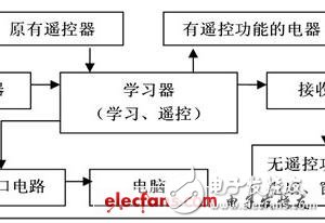
The overall principle block diagram is shown in Figure 2: